Pin fin arrangement for heat shield of gas turbine engine

Active Publication Date: 2013-03-07
PRATT & WHITNEY CANADA CORP
View PDF11 Cites 53 Cited by
  • Summary
  • Abstract
  • Description
  • Claims
  • Application Information

AI Technical Summary

Problems solved by technology

However, such rails may introduce undesirable extra contact points, extra hot spots and stiffness discontinuity and this may have an impact on the overall durability of the heat shields.

Method used


Image

  • Pin fin arrangement for heat shield of gas turbine engine
  • Pin fin arrangement for heat shield of gas turbine engine
  • Pin fin arrangement for heat shield of gas turbine engine

Examples


Embodiment Construction

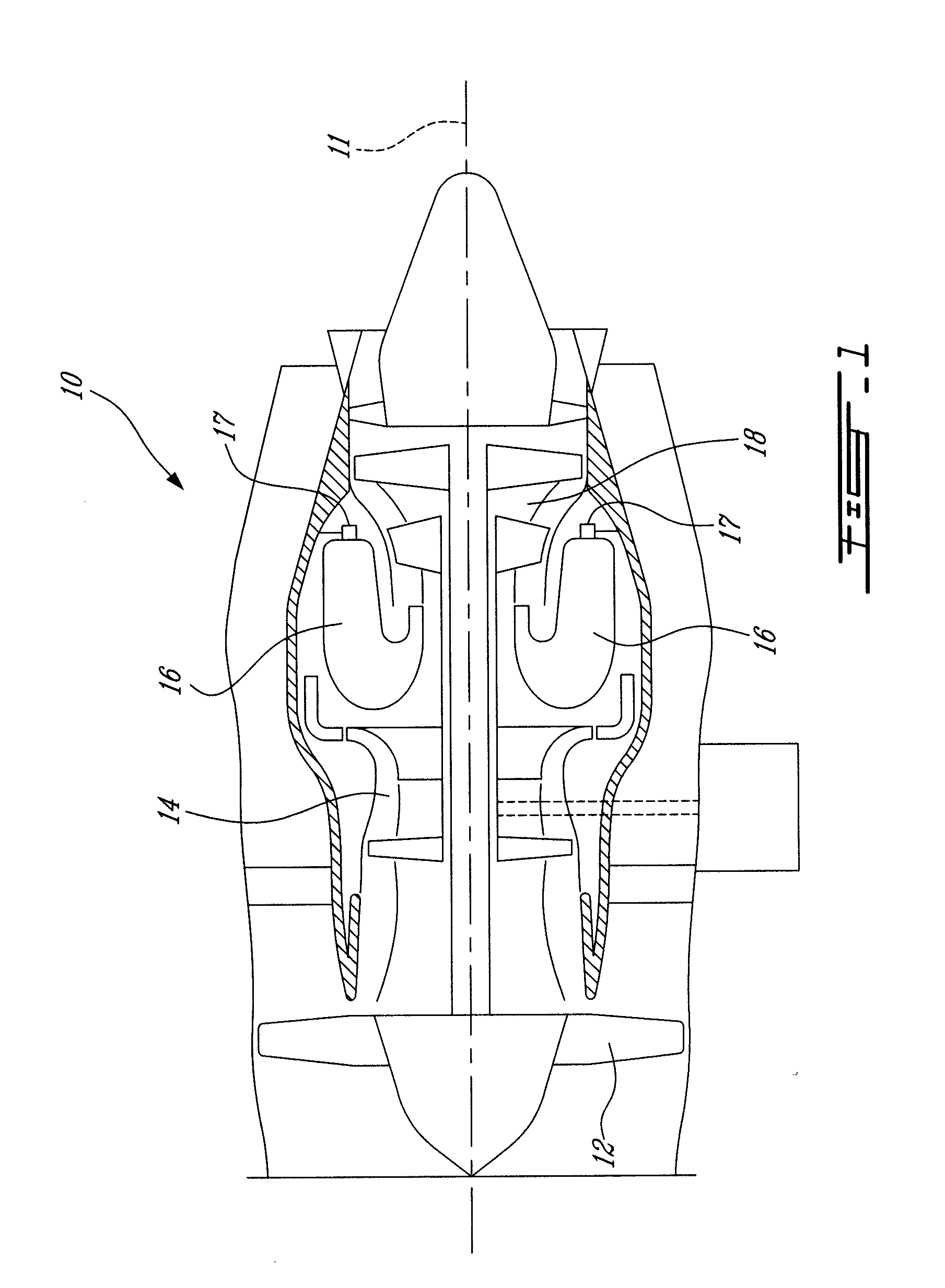
[0012]FIG. 1 illustrates a turbofan gas turbine engine 10 of a type preferably provided for use in subsonic flight, generally comprising in serial flow communication a fan 12 through which ambient air is propelled, a multistage compressor 14 for pressurizing the air, a combustor 16 in which the compressed air is mixed with fuel and ignited for generating an annular stream of hot combustion gases. Jet nozzles are illustrated at 17 relative to the combustor 16. A turbine section 18 extracts energy from the combustion gases.

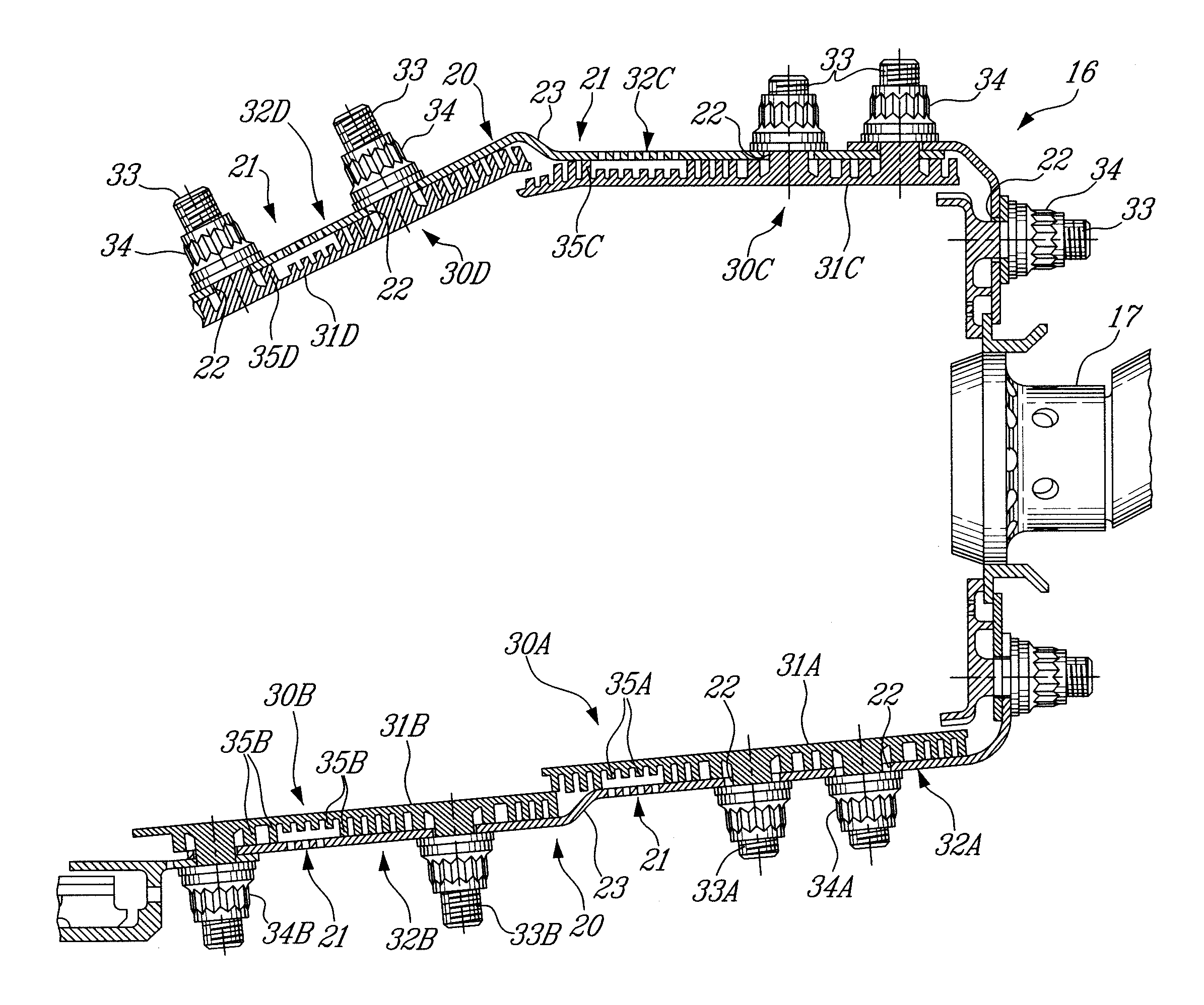
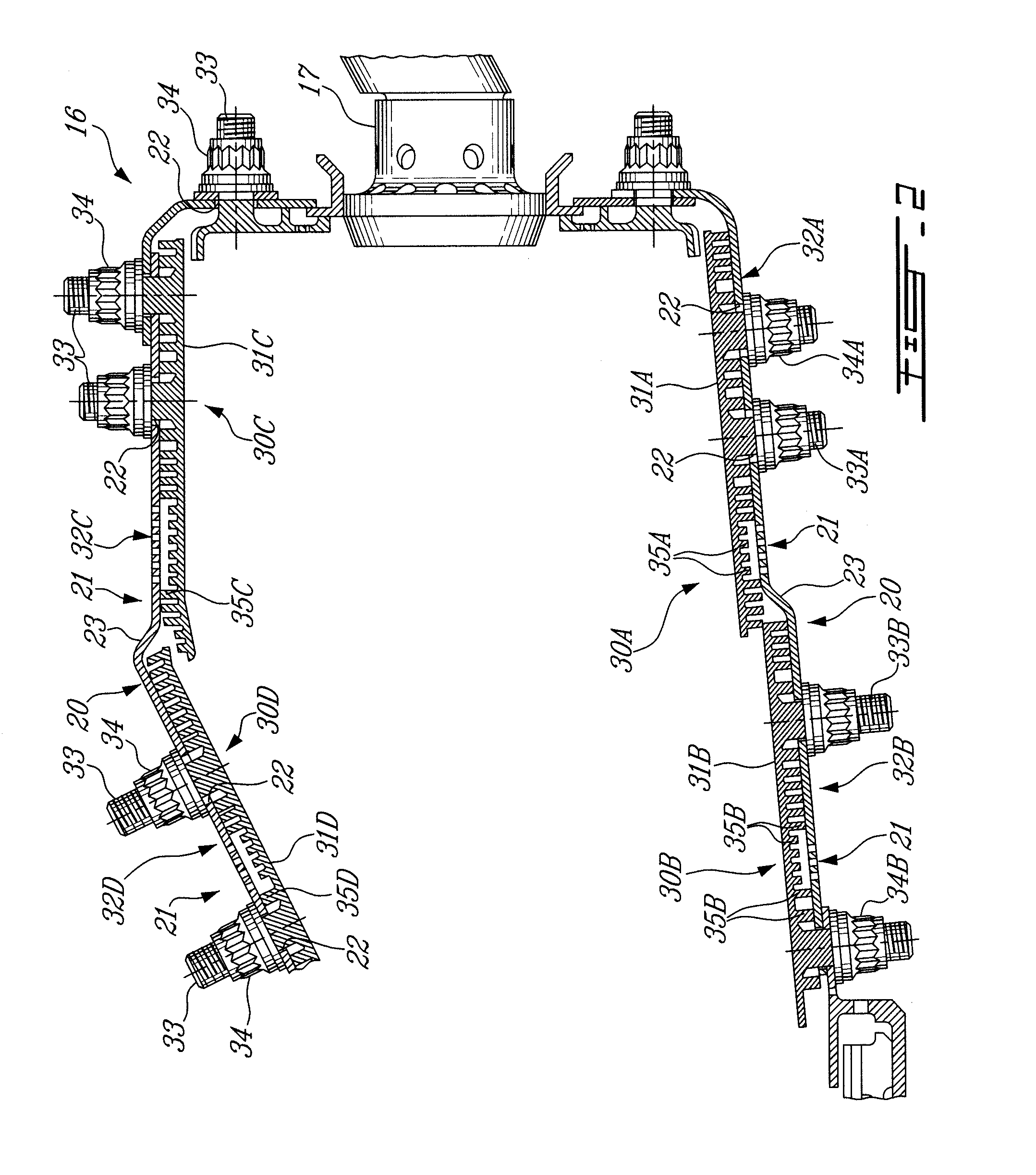
[0013]Referring to FIG. 2, a section of the combustor 16 is generally illustrated. The combustor 16 has a combustor liner 20 mounted about the fuel nozzle 17 and projecting downstream from the fuel nozzle 17. Therefore, the combustor liner 20 defines an inner volume in which combustion occurs (i.e., combustion zone). Jet apertures 21 (i.e., jets) are defined in various locations of the combustor liner 20, for the insertion of coolant fluid in the combustor 16. The j...


PUM


Abstract

A heat shield unit for a gas turbine engine combustor comprises a panel body secured to a combustor liner. A first surface of the body is oriented toward a combustion zone of a combustor. A second surface is oriented toward the liner. The body is separated into upstream and downstream portions. Pin fins project from the second surface of the body. The pin fins are arranged in arrays of at least two different densities of volume of pin fins per unit volume. One density, lower than the second density, is in the upstream portion and another in the downstream portion of the body. Connectors connect the body to the liner with a line between the upstream and downstream portions of the body aligned with fluid-coolant injection apertures in the liner. A gas turbine engine combustor and a method for cooling a heat shield unit in a combustor liner of a gas turbine engine are also provided.

Description

TECHNICAL FIELD[0001]The present application pertains to aircraft gas turbine engines and, more particularly, to heat shields found in a combustor of the gas turbine engine and to a pin fin arrangement of such a heat shield for cooling purposes.BACKGROUND OF THE ART[0002]In gas turbine engines, the combustor performance directly impacts the overall fuel efficiency of the gas turbine engine and the pollutant emission. Heat shields, also known as float walls, have therefore been provided within combustors to allow the combustor to operate at higher temperatures with relatively low combustor pressure drops. As a result, the specific field consumption of gas turbine engines is enhanced.[0003]For cooling purposes, the heat shields may be equipped with a plurality of pin fins oriented away from the combustion zone of the combustor. A coolant fluid circulates between the pin fins, thereby cooling the heat shields. Spent coolant fluid is then directed onto the exposed surface of the heat sh...

Claims


Application Information

Patent Timeline
Patent Type & Authority Applications(United States)
IPC IPC(8): F02C7/24
CPCF23R3/007F23R3/06Y02T50/675F23R2900/03042F23R2900/03044F23R3/60Y02T50/60
Inventor VERHIEL, JEFFREYSTASTNY, HONZASZE, ROBERT
Owner PRATT & WHITNEY CANADA CORP
Why Eureka
Try Eureka