Assembling method of roller bearing

An assembly method and roller bearing technology, applied in the assembly field of roller bearings, can solve the problems of complex mold shape and opening and closing control, and increase manufacturing cost, so as to suppress the forming cost, suppress the mold cost, and reduce the possibility of cracks Effect

Inactive Publication Date: 2008-12-24
NTN CORP
View PDF0 Cites 8 Cited by
  • Summary
  • Abstract
  • Description
  • Claims
  • Application Information

AI Technical Summary

Problems solved by technology

However, when the material of the spacer 8 is made of resin and produced by injection molding, such a gap 9 becomes an undercut shape, which complicates the shape of the mold and the opening and closing control, and increases the manufacturing cost.

Method used


Image

  • Assembling method of roller bearing
  • Assembling method of roller bearing
  • Assembling method of roller bearing

Examples


Embodiment Construction

[0033] Embodiments of the present invention will be described below with reference to the drawings.

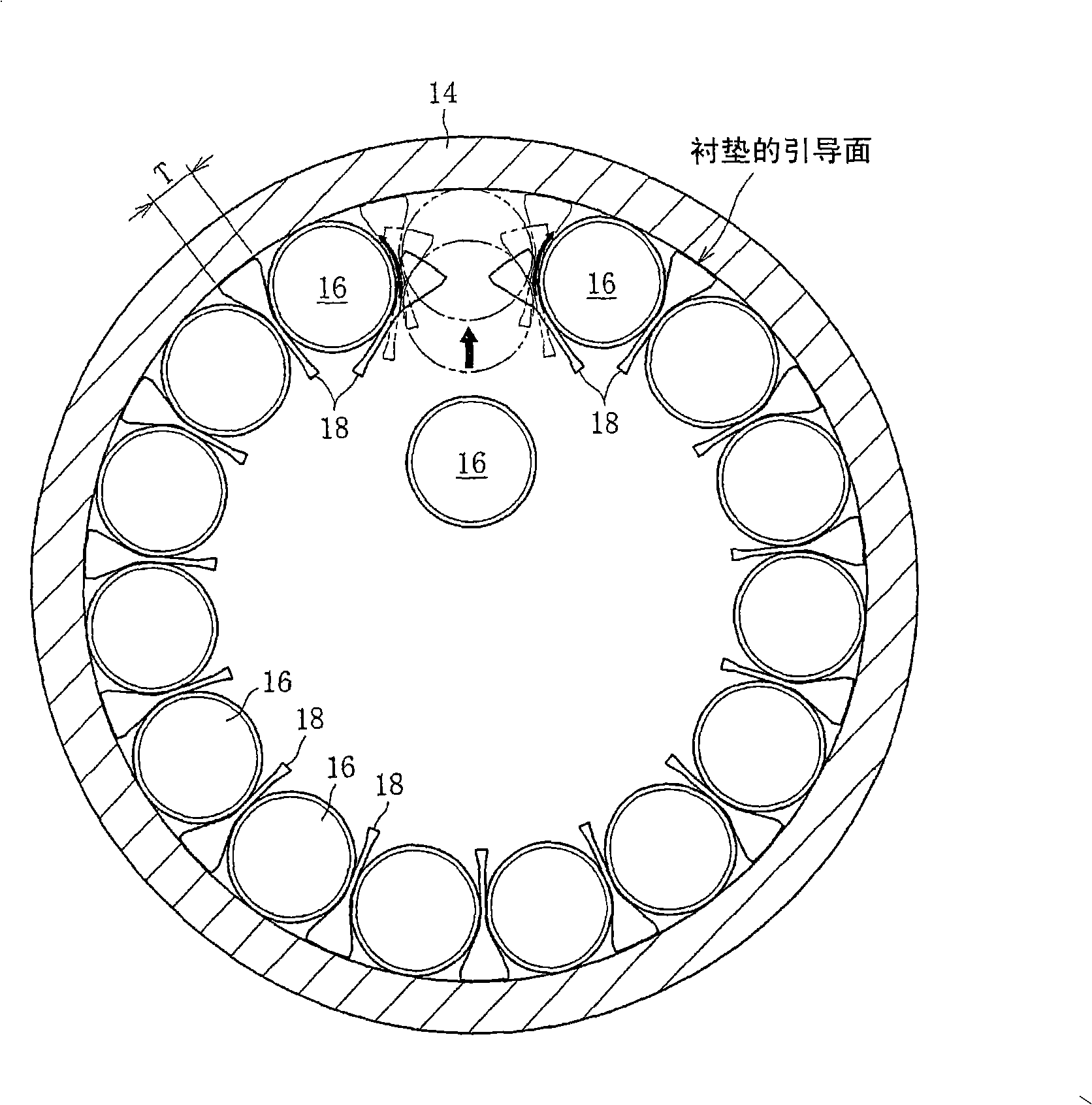
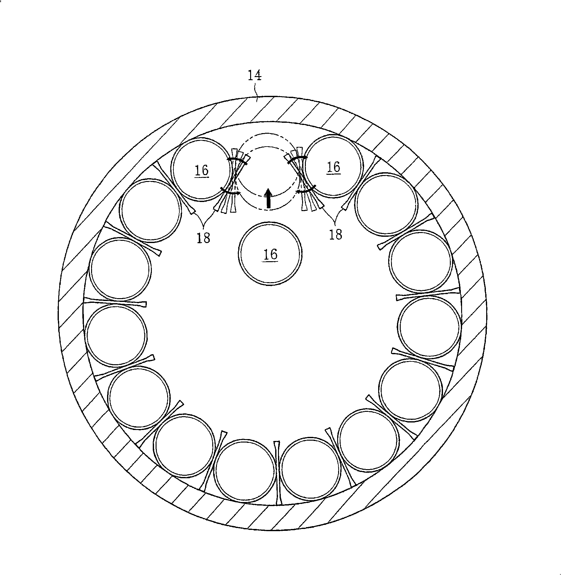
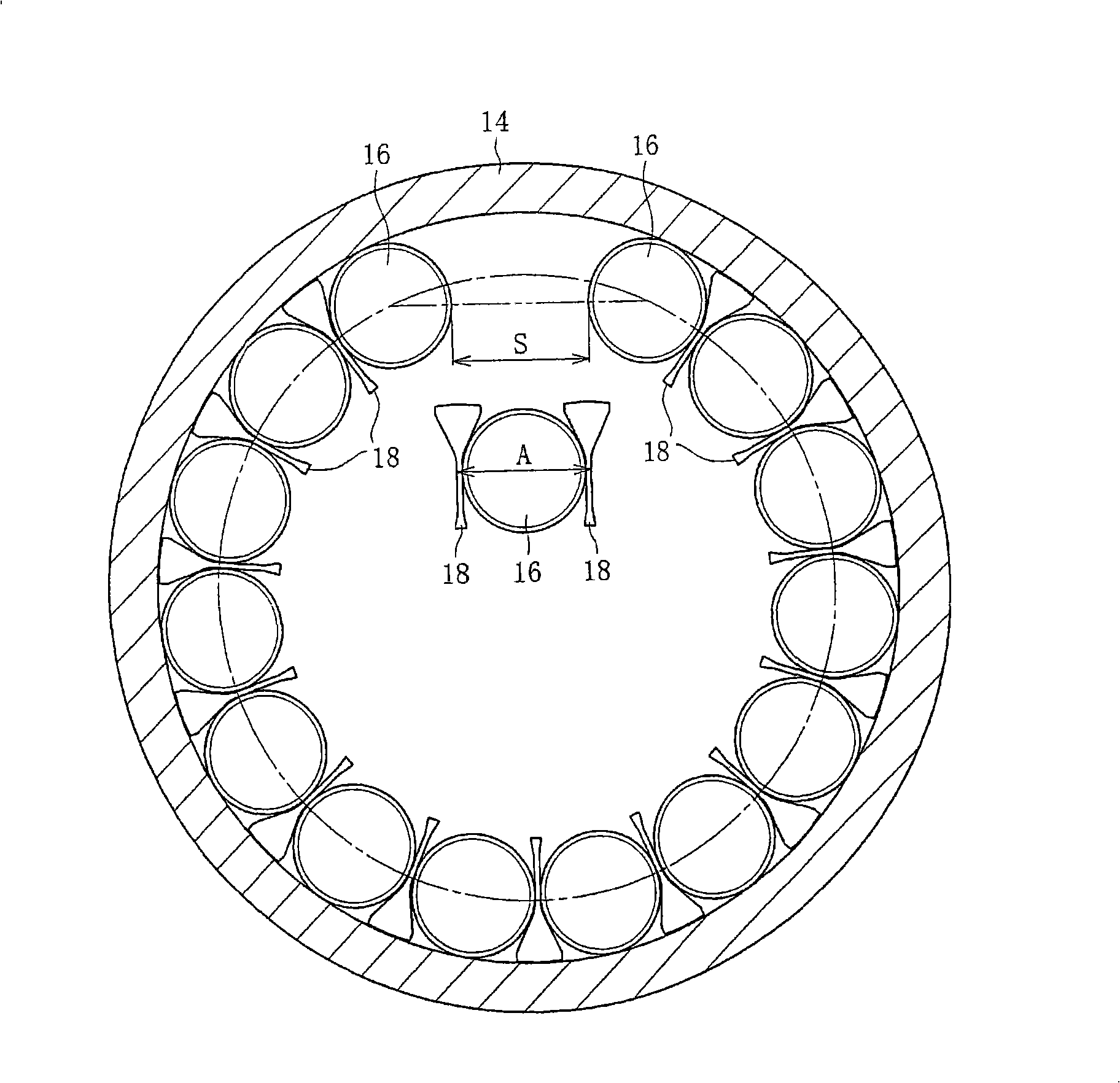
[0034] Such as figure 1 As shown, the case of applying to cylindrical roller bearings will be explained as an example. figure 1 Indicates the assembly process of cylindrical roller bearings. The assembly sequence is: Alternately arrange the rollers 16 and liners 18 on the inner periphery of the outer ring 14, and place the liners 18 that should be located on the two ribs of the last loaded roller 16 along the rolling surface 16a of the arranged rollers 16. After the inner diameter side of the bearing, the last roller 16 is pushed into the outer ring 14 so that the pads 18 of both ribs can be slid and the roller 16 can be incorporated.

[0035] The surface of the pad 18 that faces the roller rolling surface 16a, that is, the roller contact surface 18b has a concave shape that accommodates the roller rolling surface 16a. here, in figure 1 In the section perpendicular to t...


PUM


Abstract

A method of assembling a roller bearing having intermediate members placed between rollers, with which method the bearing can be assembled without elastic deformation of the intermediate members or with a minimum necessary amount of elastic deformation. Rollers (16) and intermediate members (18) are alternately arranged on the inner circumference of the outer ring (14). Then, a roller (16) to be assembled into place at the end of the bearing assembly is inserted toward the outer ring (14). This causes the rollers (16) having been arranged to be assembled into the inner circumference of the outer ring (14) while the intermediate members (18) located at both sides of the roller (16) are allowed to slide. In this process, the intermediate member (18) positioned on both sides of the roller (16) to be assembled at the end are kept set along the bearing bore side of the rolling surfaces on which the rollers (16) having been arranged roll.

Description

technical field [0001] The present invention relates to a roller bearing, and more particularly to a method for assembling a roller bearing in which a pad is sandwiched between rollers without a cage. Background technique [0002] Patent Document 1 exemplifies a roller bearing in which a spacer is interposed between adjacent rollers. Its assembly method is as Image 6 As shown, the rollers 6 and spacers 8 are alternately arranged on the inner periphery of the outer ring 4, and the last spacer 8 is pushed between the rollers 6 from the inner diameter side to the outer diameter side. At that time, the spacer 8 is press-fitted across the narrowest gap between the rollers 6 while compressing and deforming in the circumferential direction. [0003] Patent Document 1: Patent No. 3549530 [0004] Therefore, from the perspective of the relationship of the press-fit margin, the liner 8 whose wall thickness greatly exceeds the minimum gap between the rollers 6 cannot be used, becaus...

Claims


Application Information

Patent Timeline
Patent Type & Authority Applications(China)
IPC IPC(8): F16C43/06F16C19/26F16C33/372
CPCF16C19/26F16C19/40F16C33/3706F16C43/06F16C2240/80F16C2240/46Y10T29/49679
Inventor 小津琢也
Owner NTN CORP
Why Eureka
Try Eureka