Suspension arm attachment structure

A technology for mounting structures and suspension arms, which is applied to suspensions, substructures, and cantilevers mounted on pivots, etc., to achieve the effects of increased strength and rigidity, and improved installation accuracy

Active Publication Date: 2012-11-14
HONDA MOTOR CO LTD
View PDF7 Cites 8 Cited by
  • Summary
  • Abstract
  • Description
  • Claims
  • Application Information

AI Technical Summary

Problems solved by technology

Therefore, it is difficult to install the bushing contact surface of the stopper member parallel to the end surface of the vibration-proof bushing
For example, even if the spring characteristics of the anti-vibration bushing when the end face of the anti-vibration bush abuts against the bushing contact surface of the stopper member are set, depending on the mounting state of the stopper member, the end face of the anti-vibration bushing and the stopper member may be different. When one end of the bushing contact surface of the movable member contacts and the spring characteristic of the intended anti-vibration bushing cannot be exerted

Method used


Image

  • Suspension arm attachment structure
  • Suspension arm attachment structure
  • Suspension arm attachment structure

Examples


Embodiment 1

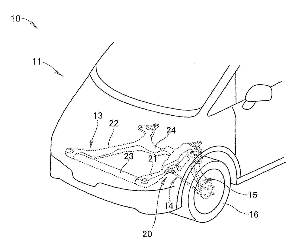
[0040] Reference figure 1 and figure 2 , The vehicle 10 includes: a front sub-chassis 13, which is mounted on the vehicle body 11, and supports an engine (not shown), a gear box (not shown), etc.; a suspension arm 14 that is swingably supported on the front sub-chassis 13; steering knuckle 15, which is supported by the suspension arm 14; wheels 16, which are mounted on the steering knuckle 15.

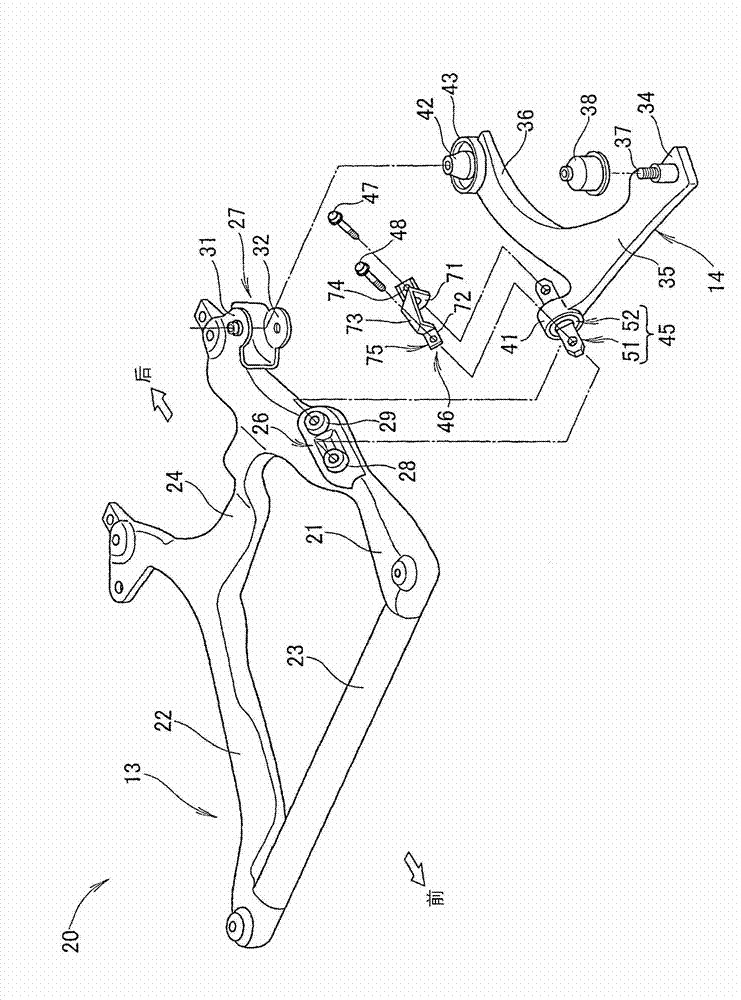
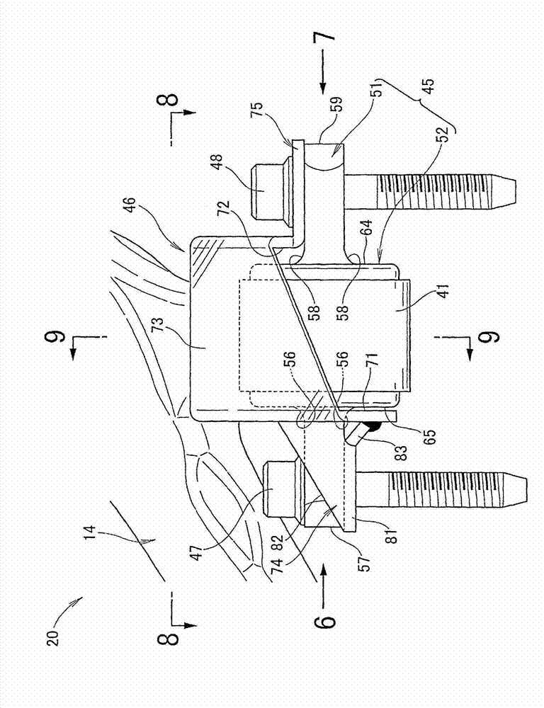
[0041] The suspension arm mounting structure 20 includes: a suspension arm 14 which is mounted on the vehicle body 11 and connected to the steering knuckle 15 supporting the wheels 16; and a mounting tube portion 41 which is provided on the suspension arm 14 and swingably supported on the vehicle body 11; Cylindrical anti-vibration bushing 52, which is fitted into the mounting tube portion 41, and is mounted to the vehicle body 11 via the core member 51; a stop member 46, which restricts the axial movement of the mounting tube portion 41.

[0042] The core member 51 is attached to the fron...

Embodiment 2

[0072] Next, combine Figure 13 ~ Figure 15 The suspension arm mounting structure 100 of the second embodiment will be described. For the suspension arm mounting structure 20 ( Figure 1 ~ Figure 12 For the common components used in ), the symbols are misappropriated and the detailed description is omitted.

[0073] Reference Figure 13 ~ Figure 15 , The suspension arm mounting structure 100 includes a front sub-chassis 13 ( figure 2 ), the forearm support portion 26, the suspension arm 14, the mounting cylinder portion 41 of the suspension arm 14, the vibration-proof bushing 52, the anti-drop member 106, and the bolts 47 and 48. The anti-vibration bush assembly 45 includes a core member (shaft) 51, an anti-vibration bush 52, and an outer tube 53.

[0074] The anti-drop member 106 has: the other side opposed wall 112 and the one side opposed wall 111 respectively corresponding to the end surfaces 64 and 65 of the anti-vibration bush 52; and the above-mentioned one side opposed w...


PUM


Abstract

Disclosed is a suspension arm attachment structure provided with a cylindrical vibration-damping bush which is attached to the side of a vehicle body via a core member. Specifically disclosed is an attachment structure provided with: a suspension arm (14) which has an attachment tube part (41) fitted with a vibration-damping bush (52); and a retaining member (46) which regulates the movement of the attachment tube part (41) in the axial longitudinal direction. The retaining member (46) is provided with: a facing wall (71) on one side and a facing wall (72) on the other side which respectively face end surfaces (64, 65) of the vibration-damping bush (52); a linking part (73) which integrally links the facing wall (71) on one side and the facing wall (72) on the other side; and an attachment part (74) on one end and an attachment part (75) on the other end which respectively extend in the axial longitudinal direction of a core member (51) from the facing surface (71) on one side and the facing surface (72) on the other side and which are attached to the side of a vehicle body (11).

Description

Technical field [0001] The present invention relates to a suspension arm mounting structure provided with a cylindrical anti-vibration bush, which is fitted into an installation tube portion of the suspension arm and is mounted on the vehicle body side via a core member. Background technique [0002] This type of suspension arm mounting structure adopts the following structure: a mounting cylinder is formed at the end of the suspension arm (lower arm), a vibration-proof bushing is fitted into the mounting cylinder, and the shaft of the vibration-proof bushing is formed Both ends of the core member are mounted to suspension elements formed on the vehicle body side. Both ends of the core member are respectively mounted on the suspension element via bolts of different body stop members. [0003] According to the above-mentioned suspension arm mounting structure, when an excessive input is applied to the suspension arm from the wheel side, the stopper member is used to prevent the mou...

Claims


Application Information

Patent Timeline
Patent Type & Authority Applications(China)
IPC IPC(8): B60G7/00B62D21/00B60G7/02
CPCB62D21/11B60G7/02B60G2204/143B60G2206/8207
Inventor 冈本公雄
Owner HONDA MOTOR CO LTD
Why Eureka
Try Eureka