Pruning machine

A technology of a pruning machine and a casing is applied in the field of pruning machines, which can solve the problems of insufficient firmness and easy falling off, and achieve the effects of convenient manufacture, simple and reliable operation, and good work safety and reliability.

Inactive Publication Date: 2008-12-31
沈高明
View PDF3 Cites 10 Cited by
  • Summary
  • Abstract
  • Description
  • Claims
  • Application Information

AI Technical Summary

Problems solved by technology

There is also a pruning machine with a patent number of 200520116978.0, which includes an organic casing, an electric motor is installed in the casing, an upper and lower blade set driven and connected to the output shaft of the electric motor, a switch button and a power supply part for controlling whether the electric motor works or not , it is characterized in that a jack is formed at the rear end of the casing for the insertion of the connecting rod, and an electrical connecting plug is installed in the jack, correspondingly, the connecting rod is provided with an electrical connecting socket at the insertion end, and the plug and the socket are electrically connected. Connection, and there is a button on the handle on the upper part of the connecting rod. Below the button is a matching trigger switch. The trigger switch forms a control power circuit through wires, plugs, sockets and motors. It extends the handle, broadens the use range of the pruning machine, and is easy to use and carry. , in the actual use process, there are still many flaws in the ointment, such as the need to modify the control circuit of the pruning machine, the circuit part needs to be added to the extension handle, which causes troubles in manufacturing, and there is a socket on the handle of the case, Especially if it is used in the wild, there may be unsafe hidden dangers in case of rain or humidity. The connecting rod is plugged into the pruning machine, which is not strong enough and easy to fall off. Therefore, further improvement of the design is needed.

Method used


Image

  • Pruning machine
  • Pruning machine
  • Pruning machine

Examples


Embodiment Construction

[0025] The present invention will be further described in detail below in conjunction with the accompanying drawings and embodiments.

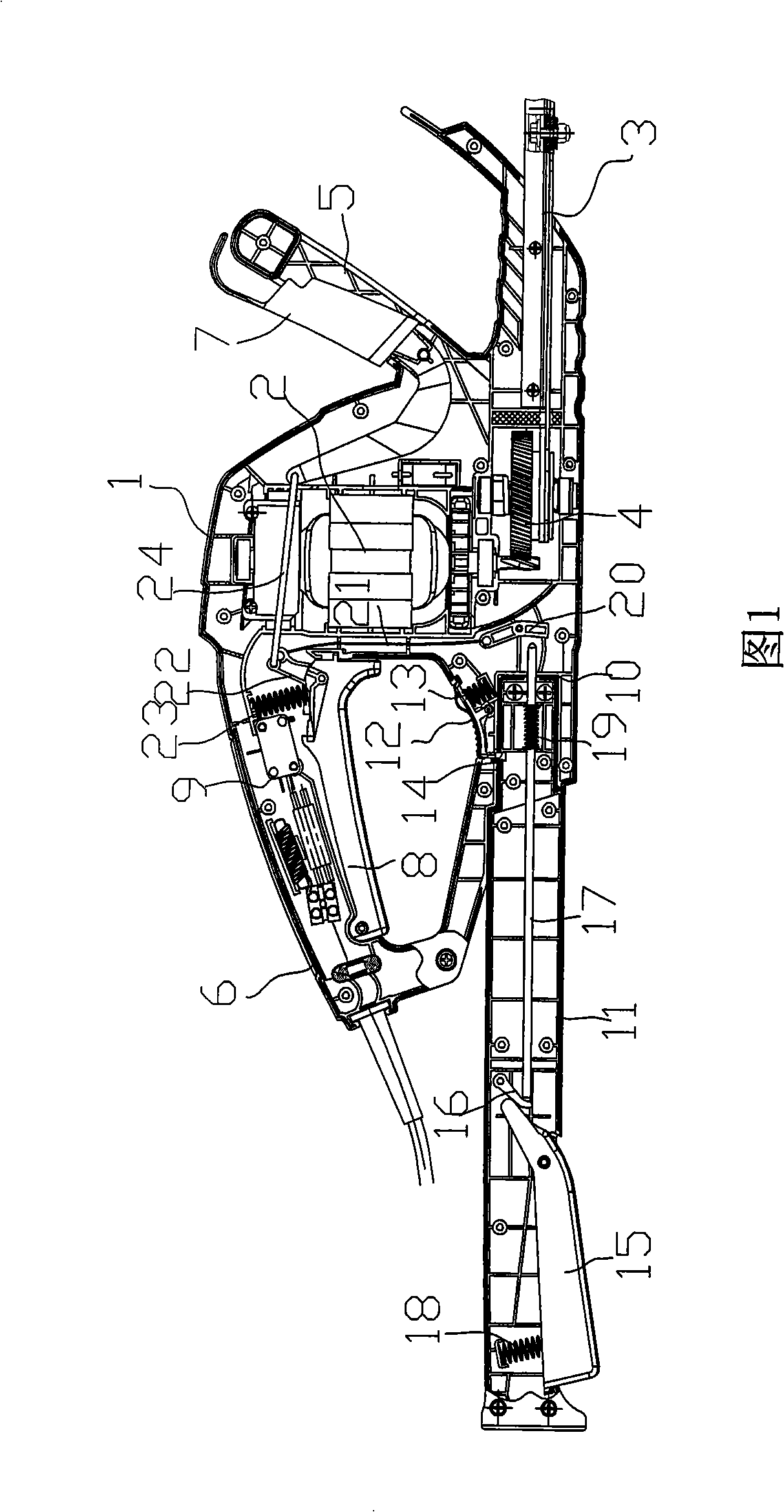
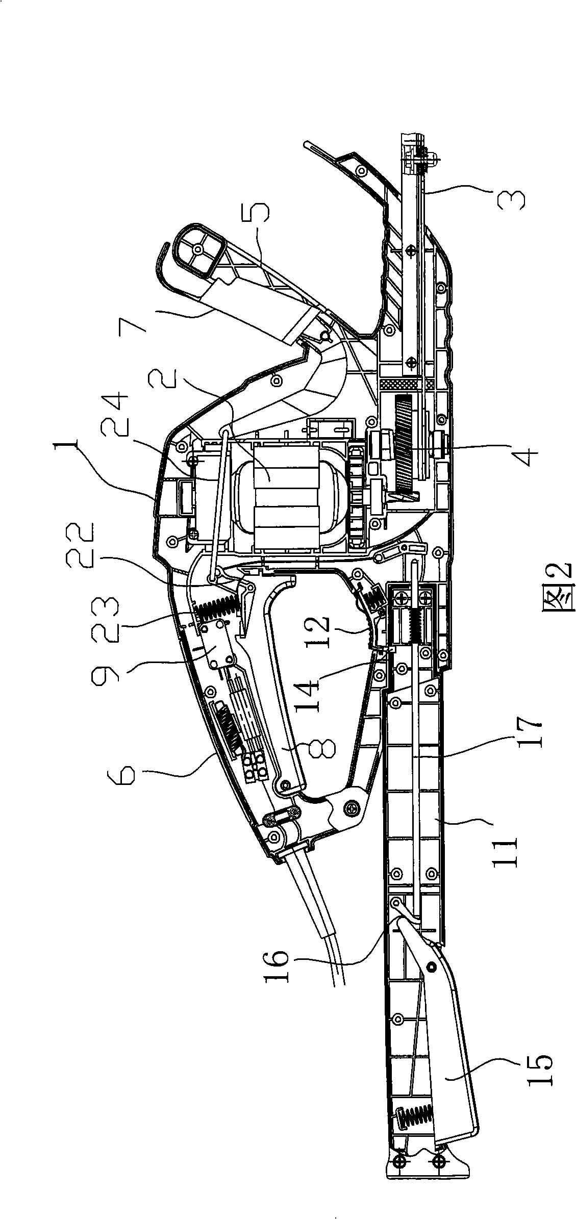
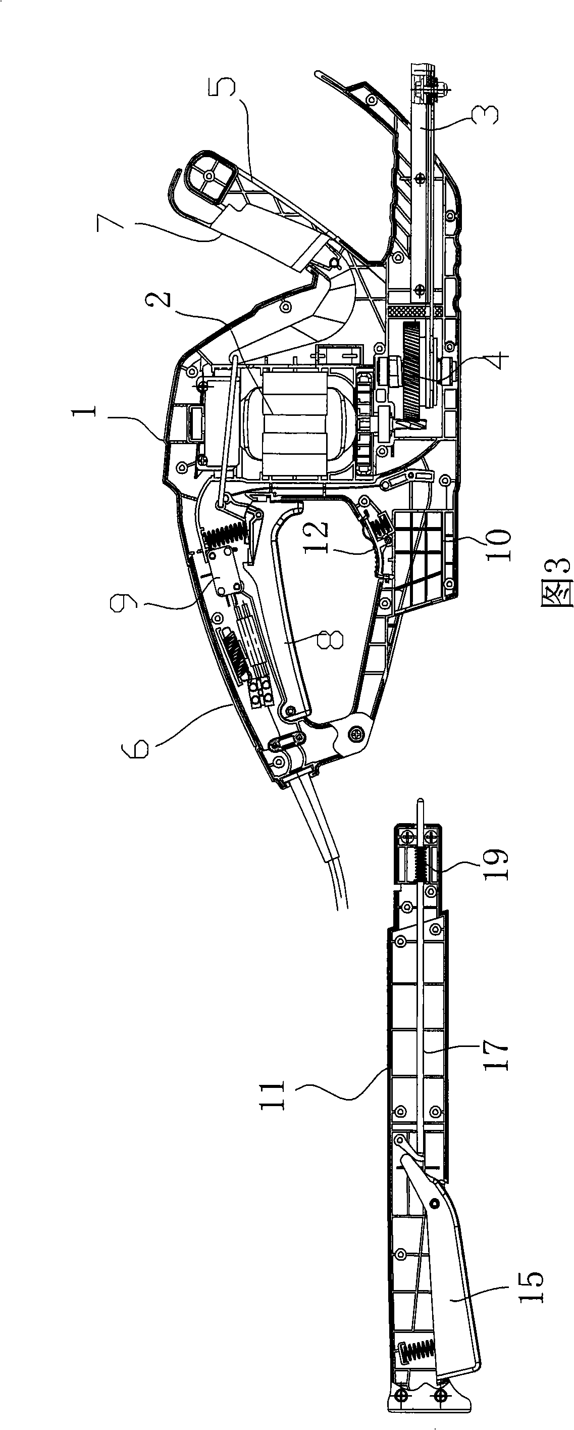
[0026] As shown in Figure 1-5, a pruning machine includes an organic casing 1. The casing 1 is usually assembled and connected with screws after the left and right casings are combined. The motor 2 is installed in the casing 1. The motor The output shaft of 2 is connected through the transmission mechanism 4 to drive the upper and lower blades 3 that reciprocate outside the casing 1. The rear and front of the casing 1 are usually connected with a rear handle 6 and a front handle 5, and in The rear handle 6 and the front handle 5 are respectively rotatably hingedly connected with a rear trigger 8 and a front trigger 7. Correspondingly, a micro switch 9 for controlling whether the motor works or not is installed in the casing 1 or the handle. Make the rear trigger 8 and the front trigger 7 cooperate with the contacts of the micro switch 9 throug...


PUM


Abstract

The invention relates to a pruner. The pruner comprises a shell; a motor is arranged in the shell; a microswitch which can control the work of the motor is installed in the shell or a handgrip; a rear trigger coordinates with a front trigger by the contact of a trigging control mechanism and the microswitch. The pruner is characterized in that a prolonged auxiliary handle is connected to the rear of the lower part of the shell in a discharge way; an auxiliary handle trigger is rotatably articulated at the position of the handgrip at the rear part of the prolonged auxiliary handle; the front end of the auxiliary handle trigger coordinates with and touches a handspike in the prolonged auxiliary handle directly or indirectly; a spring is supported between the handspike and the prolonged auxiliary handle so as to lead the other end of the handspike to touch and coordinate with one end of a dwang articulated in the shell; the other end of the dwang is connected with the triggering control mechanism by an inhaul cable or a connecting bar. The prolonged handle can be disassembled and can prune the gardens with higher height and wider scope without relying on other auxiliary equipment; only a mechanism is adopted for control, thus being safe and reliable.

Description

technical field [0001] The invention relates to a pruning machine. Background technique [0002] The pruning machine is a kind of device of garden tools, which has the advantages of strong operability and convenient use, and can realize the garden trimming to a certain height. Especially with the continuous improvement of people's living standards, the requirements for greening are getting higher and higher, so the demand for pruning machines is also increasing. [0003] Chinese patents have certain technical reports on the pruning machine, such as the safety control mechanism of the pruning machine with the patent No. 03231441.8 and the safety control mechanism of the pruning machine with the patent No. 03232415.4, for joint control through the buttons on the main handle and the auxiliary handle The control mechanism of the pruning machine has been technically reported. It can be seen that the safety control mechanism has been widely used in the pruning machine, and variou...

Claims


Application Information

Patent Timeline
Patent Type & Authority Applications(China)
IPC IPC(8): A01G3/037A01G3/025
Inventor 沈高明
Owner 沈高明
Why Eureka
Try Eureka