
Automatic insert equipment of nut

An automatic nut insertion technology, applied in the direction of metal processing equipment, metal processing, manufacturing tools, etc., can solve the problems of crimping cylinder damage, long working hours, nuts cannot be inserted into the display shell, etc., to increase production quantity, prevent failures and broken effect

Inactive Publication Date: 2008-12-31
金度完
View PDF0 Cites 5 Cited by
  • Summary
  • Abstract
  • Description
  • Claims
  • Application Information

AI Technical Summary

Problems solved by technology

[0005] For the above-mentioned conventional insertion equipment, when the worker completes the nut insertion process and replaces the display case, the fixed cylinder formed above the jig will become an obstacle, so it takes a long time to work. After a long time of work, the preheater produces High temperature will be conducted to the crimping cylinder in contact with the preheater, resulting in frequent breakage and failure of the crimping cylinder
In addition, the time required to insert a nut is too long due to heating each nut individually
[0006] In particular, the frequent breakage and failure of the crimping cylinder due to the high temperature of the preheater will cause the nut inserted into the display case to not be fully inserted, so that the inserter cannot be completely retracted, and the nut cannot be inserted into the display case and other products frequently. Quality problems, there is no guarantee that the insertion process will be carried out automatically and smoothly

Method used


Image

  • Automatic insert equipment of nut
  • Automatic insert equipment of nut
  • Automatic insert equipment of nut

Examples


Embodiment Construction

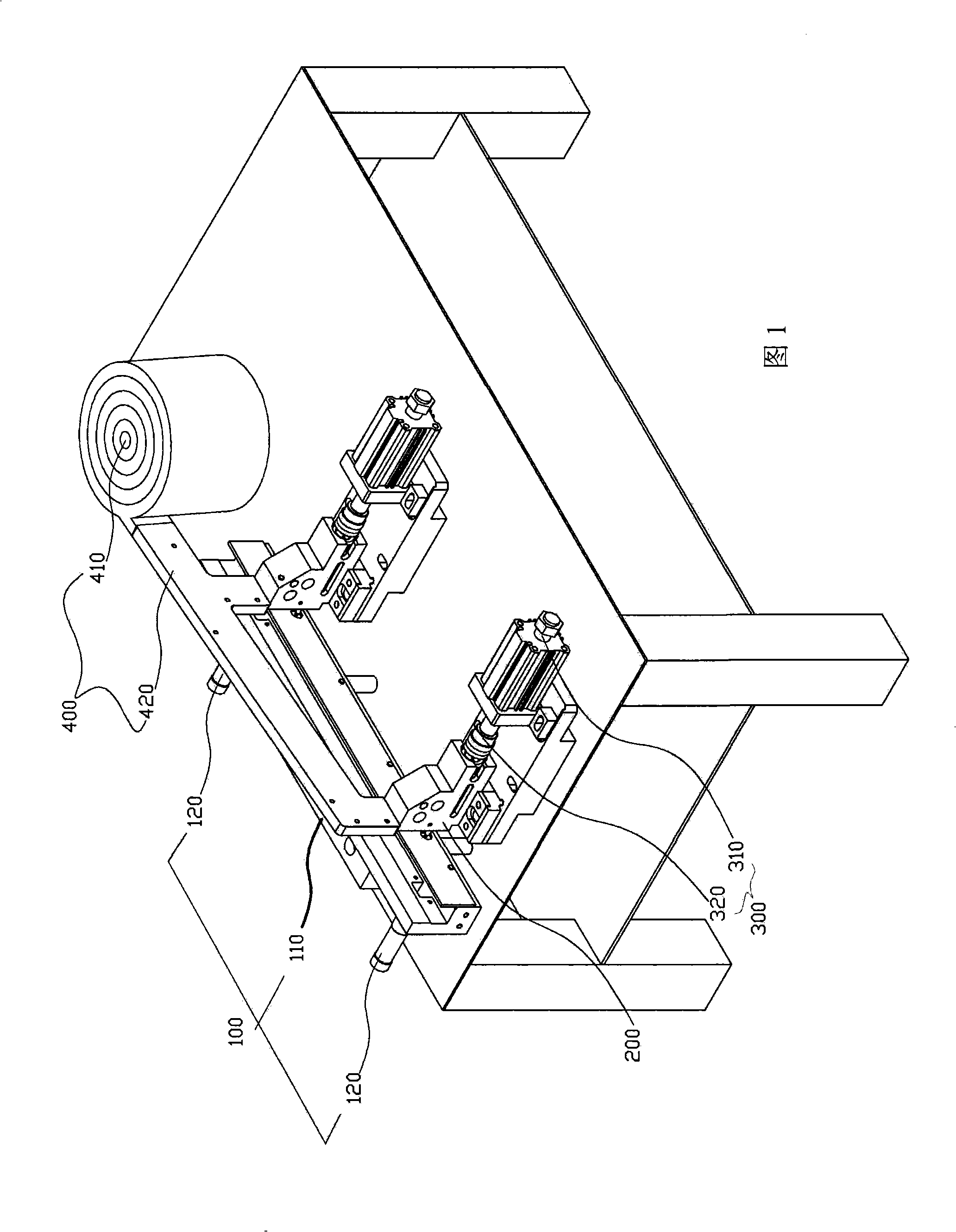
[0021] Hereinafter, an embodiment of the present invention using a general support frame having mutually symmetrical nut portions formed on one side and two nuts respectively inserted will be described in detail with reference to the accompanying drawings.

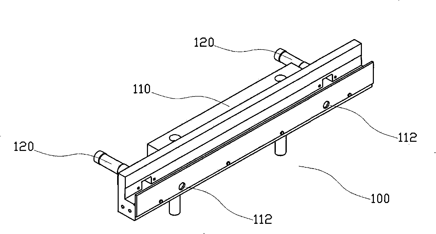
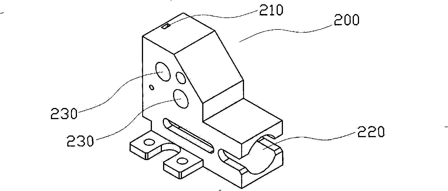
[0022] Fig. 1 is the three-dimensional schematic diagram of the embodiment of the present invention; figure 2 It is a detailed three-dimensional schematic diagram of the fixture of the present invention; image 3 It is a detailed structural perspective view of the preheater of the present invention; Figure 4 It is a three-dimensional schematic diagram of the detailed structure of the inserter 320 of the present invention; Figure 5 It is a three-dimensional schematic diagram of the detailed structure of the feeder of the present invention; Figure 6 It is a three-dimensional schematic diagram of the combination relationship between the interposer 320 and the preheater 200 of the present invention; Figure 7 It is a sch...


PUM


Abstract

The invention relates to an automatic insertion equipment of nut, comprising a clamper, a preheater, a compression joint device and a supplier. The clamper has a fixed circular cylinder working horizontally, and a nut hole formed on the surface opposite to that arranged with the fixed circular cylinder. The preheater is arranged in the front opposite to the nut hole of the clamper, having heater, a nut groove is vertically formed on the upper surface of one side of the preheater and an insertion hole is horizontally formed to intersect with the nut groove. The compression joint device is arranged on the rear part of the preheater, comprising the fore-and-aft movable compression joint circular cylinder and the inserter combined with the piston end of the compression joint circular cylinder. The supplier is arranged on the upper part of the nut groove, comprising an external member and a feeder. Because the fixed circular cylinder works horizontally, the support can be easily replaced so as to improve the production efficiency; and multiple nuts can be simultaneously heated so as to greatly reduce work hours.

Description

technical field [0001] The present invention relates to a nut automatic inserting device for fixing nuts on a support frame for fixing an LCD panel, in particular, it relates to a support frame that can be easily replaced by a worker, while the support frame will not be detached from the fixture, and can prevent heating of the nut The high temperature of the preheater is transmitted to other parts, causing damage or failure of other parts. The nut is automatically inserted into the device. Background technique [0002] Generally, the support frame used to fix the LCD panel to the display is inserted into the nut after injection molding of plastic resin. When inserting, the nut is heated to a high temperature before being inserted into the designated nut of the support frame formed of plastic resin. The fixing part is inserted by melting a part of the support frame formed of plastic resin by the high temperature of the nut, and as the nut cools, the plastic resin solidifies a...

Claims


Application Information

Patent Timeline
IPC IPC(8): B29C65/78B29C65/02
CPCB23P19/06B23P19/10B29C45/14
Inventor 金度完
Owner 金度完
Learn More