Manufacturing process of vacuum glass

A technology of vacuum glass and manufacturing process, which is applied in the direction of glass manufacturing equipment, manufacturing tools, glass forming, etc., and can solve problems affecting the quality of vacuum glass, insufficient vacuum degree, complex structure, etc., to achieve continuous production and improve vacuum degree , the effect of large operating space

Active Publication Date: 2013-06-26
TIANJIN GUSHANG VACUUM GLASS MFG
View PDF4 Cites 1 Cited by
  • Summary
  • Abstract
  • Description
  • Claims
  • Application Information

AI Technical Summary

Problems solved by technology

The shortcoming that above-mentioned two kinds of methods exist is: 1, in the existing vacuum heating furnace, glass supports are placed parallelly up and down, the spacing between each layer of glass supports is 15-25cm, and each layer of glass supports is equipped with a cooling water device The suction head is connected to the suction pipe installed in the vacuum glass. The vacuum unit is installed outside the furnace, and the vacuum is sealed in the furnace, thus completing the manufacture of vacuum glass. However, this structure makes the unit volume in the furnace set Complicated, few layers, low output; 2. The existing vacuum glass suction head device has a complex structure, difficult connection, easy to break, and water cooling is prone to water leakage and cause accidents; 3. The existing vacuum glass suction pipe It is a through hole. During the cooling process of the vacuum glass after edge sealing, there is still some moisture in the vacuum chamber. Although the moisture can be absorbed by the getter, there is also the problem of insufficient vacuum degree that affects the vacuum. The quality of glass; 4. The existing heating furnace and vacuum furnace have their own functions, basically there is no organic connection, and the energy consumption is relatively large

Method used


Image

  • Manufacturing process of vacuum glass
  • Manufacturing process of vacuum glass
  • Manufacturing process of vacuum glass

Examples


Embodiment Construction

[0023] The present invention will be further described in detail below in conjunction with the accompanying drawings and through specific embodiments. The following embodiments are only descriptive, not restrictive, and cannot limit the protection scope of the present invention.

[0024] In order to clearly describe the embodiment of the present invention, the manufacturing system of the present invention will be described first.

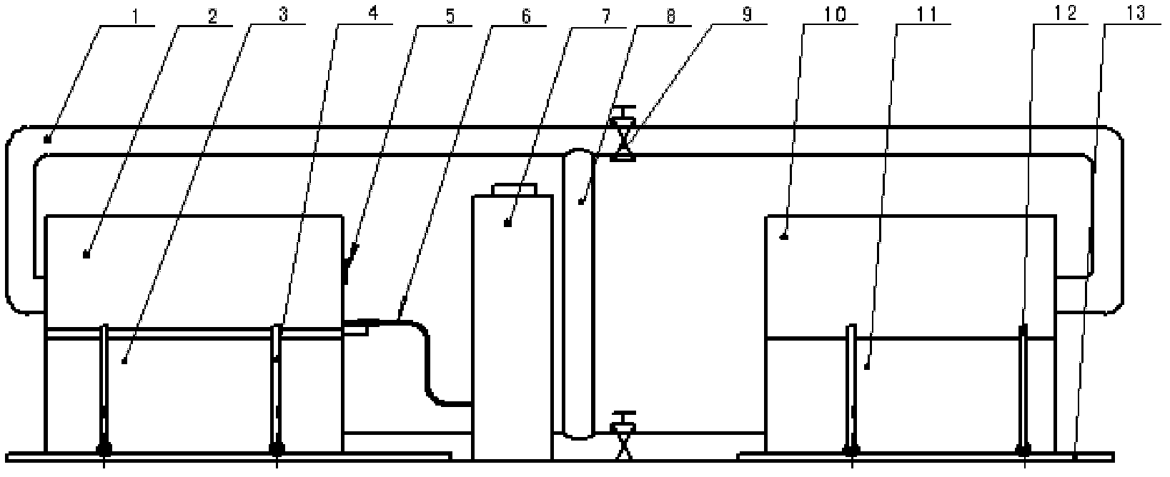
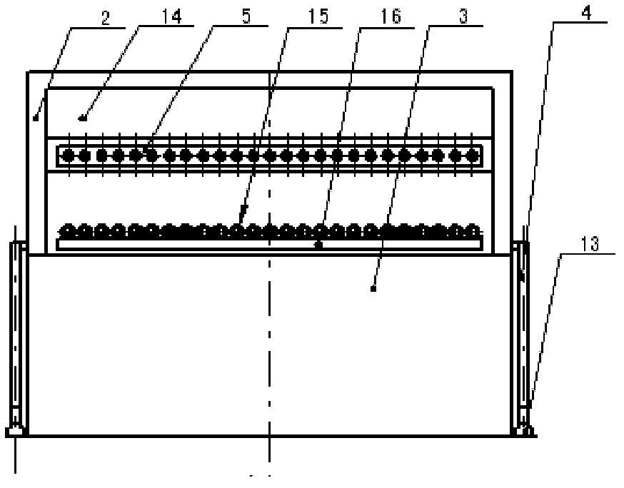
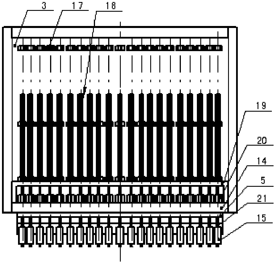
[0025] see figure 1 , 2 3. The manufacturing system includes a high-temperature heating box and a low-temperature heating furnace. The high-temperature heating box is composed of a sealing box cover door 10 and a heating box 11. The sealing box cover door is a door-type structure, and the sealing cover is installed on the heating box. The sealing box cover Both the door and the heating box are equipped with thermal insulation materials, and a mobile bracket 12 is installed on both sides of the sealed box cover door. The lower end of the mobile brac...


PUM


Abstract

The invention relates to a manufacturing process of vacuum glass, which comprises the following steps: (1) sheet binding, that is, cutting an upper and a lower piece of flat glass into sheets, placing a supporting substance between the two pieces of glass, placing a low-melting glass powder or a binder between the upper and the lower piece of flat glass, welding and mounting an air exhaust glass tube at the side edge or the side surface of the angle part, wherein the air exhaust glass tube is a sealed glass tube; (2) heating for edge sealing in a high-temperature heating box; (3) orderly placing the glass with a sealed edge into a clamping frame which is fixedly mounted on a bottom plate in an air exhaust box of a low-temperature heating furnace; (4) vacuum pumping, that is, starting a vacuum pump, performing vacuum pumping of a cavity in the vacuum glass to reach a set vacuum degree, performing hot-melt sealing of the air exhaust tube by an electrically-fusing electrode, cooling to room temperature, taking the product out of the furnace to obtain the vacuum glass. In the manufacturing process of vacuum glass, the air exhaust tube mounted in the high-temperature heating box is a blind-hole tube, and thus during the cooling process after the edge sealing of the vacuum glass, outdoor air is prevented from entering the vacuum glass cavity; the air in the cavity is maintained to be dry; the specific gravity of the air in the cavity is decreased; the vacuum degree in the cavity is increased; during the vacuum pumping of the cavity, the air exhausting efficiency is increased; procedures for removing moisture in the cavity is reduced; and the quality of the vacuum glass is guaranteed.

Description

technical field [0001] The invention belongs to the field of vacuum glass, in particular to a manufacturing process of vacuum glass. Background technique [0002] At present, the traditional vacuum glass manufacturing method is to lay supports on the substrate glass, and then combine the sheets, seal the edges, make air extraction holes, install air extraction pipes, and place the two pieces of glass flat in the heating furnace for heating and edge sealing. Then take it out for vacuuming, and after fusing the exhaust pipe, vacuum glass can be formed. Alternatively, heating and edge sealing and vacuuming can also be carried out directly in a vacuum heating furnace. The shortcoming that above-mentioned two kinds of methods exist is: 1, in the existing vacuum heating furnace, glass supports are placed parallelly up and down, the spacing between each layer of glass supports is 15-25cm, and each layer of glass supports is equipped with a cooling water device The suction head is...

Claims


Application Information

Patent Timeline
Patent Type & Authority Patents(China)
IPC IPC(8): C03B23/24C03C27/10
CPCY02P40/57
Inventor 左树森
Owner TIANJIN GUSHANG VACUUM GLASS MFG
Why Eureka
Try Eureka