
Plug cap for internal combustion engine

A technology for an internal combustion engine and a plug cap, which is applied in the field of manufacturing and processing of internal combustion engine plug caps, can solve the problems of insufficiency, low degree of automation, low efficiency and the like

Inactive Publication Date: 2019-01-04
俞李娜
View PDF0 Cites 2 Cited by
  • Summary
  • Abstract
  • Description
  • Claims
  • Application Information

AI Technical Summary

Problems solved by technology

[0002] The internal combustion engine plug cap is one of the main parts of the internal combustion engine, and its main material is rubber. The rubber molding process currently on the market is to use rubber raw materials to put them into the mold, and then heat treatment to make the rubber melt and then molded. However, at present The degree of automation in this area is low, and the efficiency is low. It is gradually insufficient to deal with the growing demand for internal combustion engine plug caps in the market. To solve the above problems, an improved design of a fully automated internal combustion engine plug cap manufacturing machine is carried out.

Method used

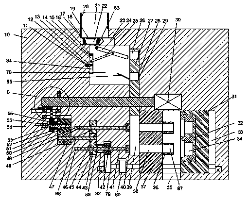
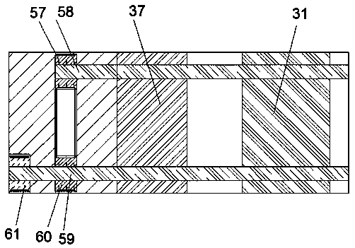
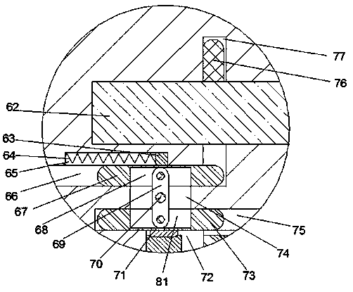

Image

  • Plug cap for internal combustion engine
  • Plug cap for internal combustion engine
  • Plug cap for internal combustion engine

Examples


Embodiment Construction

[0011] The following will clearly and completely describe the technical solutions in the embodiments of the present invention with reference to the accompanying drawings in the embodiments of the present invention. Obviously, the described embodiments are only some, not all, embodiments of the present invention. Based on the embodiments of the present invention, all other embodiments obtained by persons of ordinary skill in the art without making creative efforts belong to the protection scope of the present invention.

[0012] see Figure 1-3, an embodiment provided by the present invention: a plug cap for an internal combustion engine, including a frame 10, a raw material drop cavity 78 is provided in the frame 10, and a raw material outlet cavity is provided above the raw material drop cavity 78 23. The right side of the raw material drop chamber 78 is provided with a connected raw material conveying chamber 39, and the right side of the raw material conveying chamber 39 is...


PUM


Abstract

The invention discloses a plug cap for an internal combustion engine. The plug cap comprises a machine frame, wherein a raw material receiving cavity is arranged in the machine frame; a raw material outlet cavity is arranged on the raw material receiving cavity; a raw material conveying cavity which communicates with the raw material receiving cavity is arranged on the right side of the raw material receiving cavity; a processing cavity which communicates with the raw material conveying cavity is arranged on the right side of the raw material conveying cavity; a finished product receiving cavity which is communicated with the processing cavity and external environment is arranged under the processing cavity, and the opening of the finished product receiving cavity faces downwards; a firstpush plate translation cavity which is communicated with the raw material conveying cavity is arranged on the left side of the raw material conveying cavity; a second push plate translation cavity which is parallel to the first push plate translation cavity is arranged above the first push plate translation cavity. The plug cap disclosed by the invention is simple in structure and convenient to operate, and has the advantages that the automatic process of rubber shaping is realized; a discharge device is arranged, so that simple single discharge can be completed by a simple mechanical structure; the ductility is high, so that the production quantity of the plug caps can be increased as required by users, and the economic benefits can also be increased.

Description

technical field [0001] The invention relates to the manufacture and processing of a plug cap for an internal combustion engine, in particular to a plug cap for an internal combustion engine. Background technique [0002] The internal combustion engine plug cap is one of the main parts of the internal combustion engine, and its main material is rubber. The rubber molding process currently on the market is to use rubber raw materials to put them into the mold, and then heat treatment to make the rubber melt and then molded. However, at present The degree of automation in this area is low, and the efficiency is low. It is gradually insufficient to deal with the growing demand for internal combustion engine plug caps in the market. To solve the above problems, an improved design of a fully automatic internal combustion engine plug cap manufacturing machine is carried out. Contents of the invention [0003] The object of the present invention is to provide a plug cap for an int...

Claims


Application Information

Patent Timeline
Patent Type & Authority Applications(China)
IPC IPC(8): B29C43/02B29C43/34B29C43/52
CPCB29C43/02B29C43/34B29C43/52
Inventor 俞李娜
Owner 俞李娜
Learn More