Eureka AIR delivers breakthrough ideas for toughest innovation challenges, trusted by R&D personnel around the world.

Elastic tube-type thermal production casing head

A casing head and tubular technology, applied in the field of elastic tubular thermal mining casing heads, can solve the problems of difficult operation, leakage of heat medium, loose connection, etc., so as to reduce mining costs, ensure safe operation, installation and maintenance. Easy to use and stable effect

Inactive Publication Date: 2008-12-31
宿官礼
View PDF0 Cites 11 Cited by
  • Summary
  • Abstract
  • Description
  • Claims
  • Application Information

AI Technical Summary

Problems solved by technology

At present, the fixation and installation of heavy oil development wellheads are uniformly welded with circular steel plates. When the steam is injected, the telescopic tube is heated and expanded, and the welded seam is pushed away. In this way, the wellhead device will be in an unknown up and down in the vertical state. The telescopic tube It is also in an unconstrained state in the direction of rotation, making it difficult to control the operation and causing serious accident hazards
Especially during the installation and breakout process of the wellhead, the connection between the telescopic pipes will loosen, resulting in the leakage of the injected heat medium. In severe cases, the telescopic pipe will shoot out of the wellbore and explode into the air under the action of high temperature and high pressure medium.

Method used


Image

  • Elastic tube-type thermal production casing head

Examples


Embodiment 1

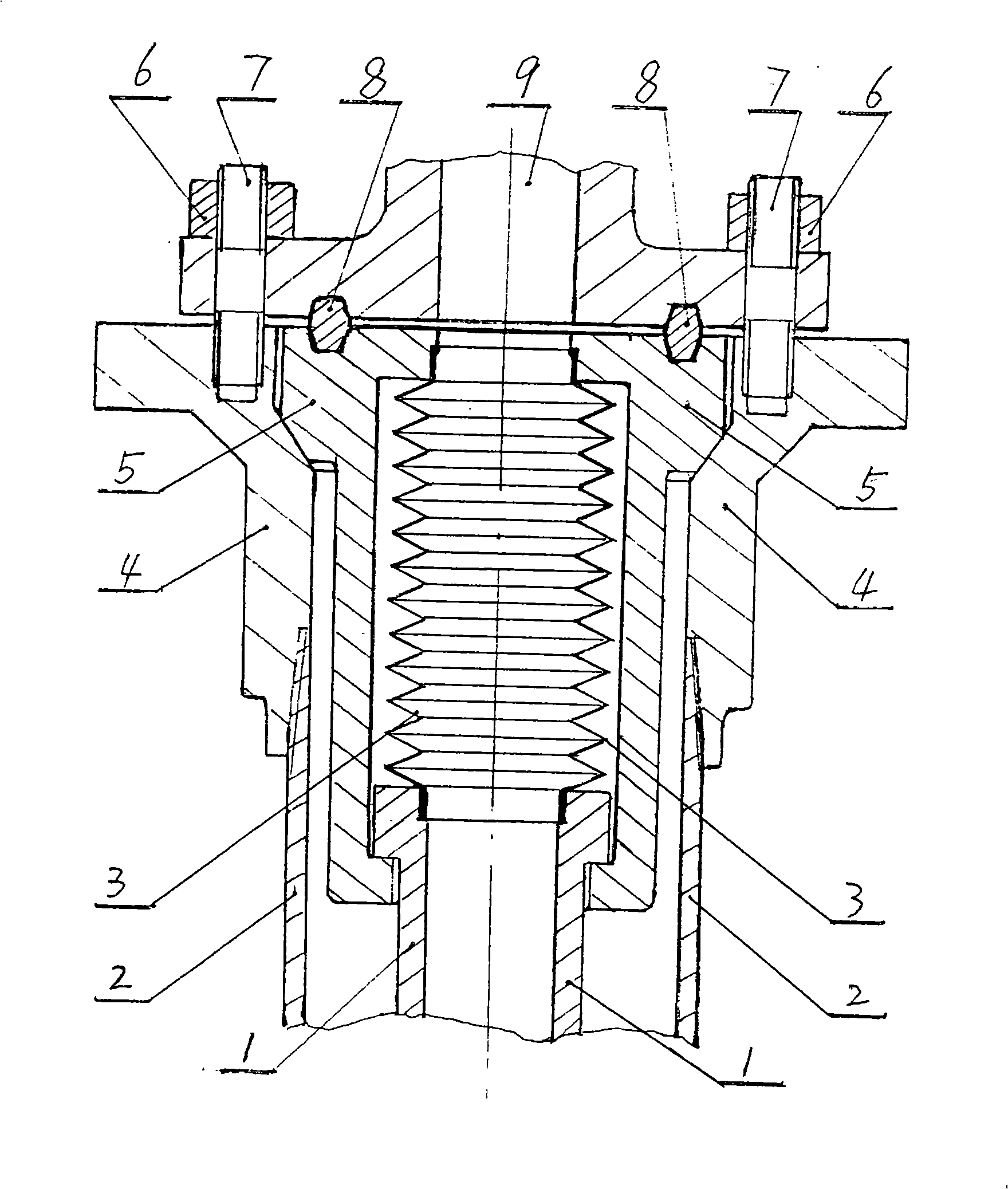
[0009] Embodiment 1: Referring to the accompanying drawings, the upper flange 9 and the lower flange 4 are connected and fixed by bolts 7 and nuts 6 . The inner strength of the lower flange 5 is inserted into the suspension body steel cylinder 5 of an integrated structure, and the top of the suspension body steel cylinder 5 is provided with a metal sealing gasket 8 on the mating surface of the upper flange 9 to increase its sealing performance under high pressure and high temperature conditions . The lower end of the suspension body steel cylinder 5 is lapped and matched with the convex edge and the convex edge of the upper end of the telescopic tube 1. Between the upper port of the telescopic tube 1 and the upper port of the suspension body steel cylinder 5, there is a hole that penetrates the inner chamber of the suspension body steel cylinder. The elastic tube 3 is used to ensure that the telescopic tube 1 is released through the elastic tube provided in the inner cavity of...

Embodiment 2

[0010] Embodiment 2: On the basis of Embodiment 1, only the steel cylinder of the suspension body is designed as a combined structure with connecting pipe fittings in the middle.

[0011] The telescopic tube referred to in the present invention is also called the inner casing, and the lower flange is also called the housing.


PUM


Abstract

The invention relates to an elastic pipe type thermal production casing head in the oil well casing connecting piece. The technical proposal includes that a lower flange is butt joint with an upper flange after a hanging steel cylinder is nested in the lower flange; the bottom end of the hanging steel cylinder is provided with a convex rim with contracted diameter; the convex edge is matched with the convex edge with expanded diameter on the periphery of the upper end part of a telescopic pipe; an elastic pipe is threaded through the inner cavity chamber of the hanging steel cylinder and connected between the upper end opening of the telescopic pipe and the upper end opening of the hanging steel cylinder; screw thread connected with the an outer casing is arranged on the lower end pipe wall of the lower flange. The elastic pipe type thermal production casing head well solves the telescopic problem of the telescopic pipe due to the thermal expansion because the elastic pipe additionally arranged in the hanging steel cylinder is connected with the telescopic pipe; thereby, the safety hidden trouble in the current welding fixation mode is solved completely. The elastic pipe type thermal production casing head has the advantages of novel integral structure design, convenient and stable mounting and application, reducing the production cost and ensuring the thermal production to operate safely.

Description

technical field [0001] The invention relates to an elastic tubular thermal recovery casing head in the field of oil well casing connectors, which is especially suitable for supporting use in thermal recovery production of heavy oil wells. Background technique [0002] Downhole heavy oil has a high development cost due to its high viscosity and poor fluidity. During the period of low oil prices, the development of heavy oil was not taken seriously, and its production technology and supporting equipment were generally in a backward and simple state. At present, the fixation and installation of heavy oil development wellheads are uniformly welded with circular steel plates. When the steam is injected, the expansion tube is heated and expanded, and the welded seam is pushed away. In this way, the wellhead device will be in an unknown up and down in the vertical state. The expansion tube It is also in an unconstrained state in the direction of rotation, which makes the operation ...

Claims


Application Information

Patent Timeline
Patent Type & Authority Applications(China)
IPC IPC(8): E21B33/04E21B43/24
Inventor 宿官礼于京阁郝友才
Owner 宿官礼
Why Eureka
Eureka Blog
Learn More