
Transparent touching control panel device

A touch panel, transparent technology, applied in instrumentation, electrical digital data processing, input/output process of data processing, etc., can solve the problems of noise, interference contact point detection, low production yield and so on

Inactive Publication Date: 2008-12-31
触控科技有限公司
View PDF0 Cites 28 Cited by
  • Summary
  • Abstract
  • Description
  • Claims
  • Application Information

AI Technical Summary

Problems solved by technology

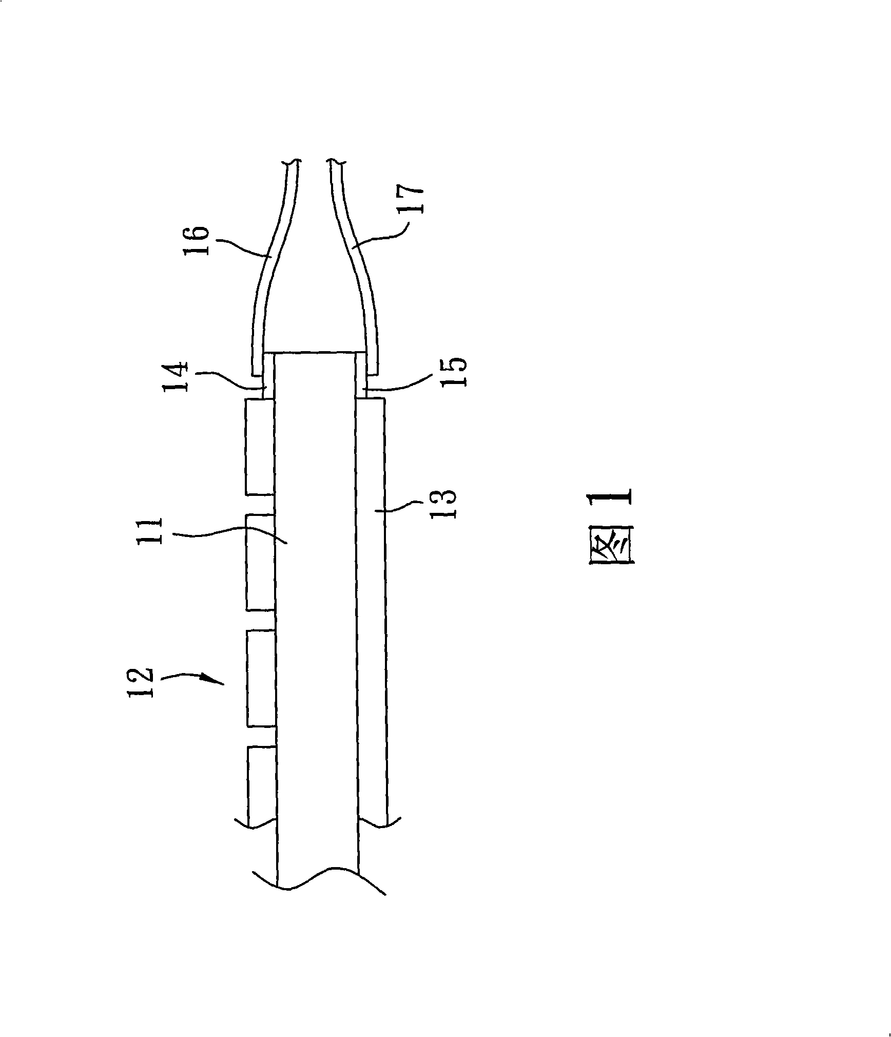
[0004] However, in the manufacturing process of the above-mentioned capacitive touch panel device, the first extension line unit 16 and the second extension line unit 17 need to be bonded respectively around the top and bottom of the substrate 11 and overlap the first extension line unit 16 and the second extension line unit 17 respectively. 1. When the second wire unit 14, 15 is used to electrically connect the first and second electrode units 12, 13, and the first and second extension wire units 16, 17 extend to the outside around the substrate 11, often due to the first and second The gap between the extension line units 16 and 17 has an indeterminate distance, which causes noise between the first and second extension line units 16 and 17, which interferes with the detection of contact points and causes a problem of low production yield.

Method used


Image

  • Transparent touching control panel device
  • Transparent touching control panel device
  • Transparent touching control panel device

Examples


Embodiment Construction

[0013] Below in conjunction with accompanying drawing and embodiment, the present invention is described in detail:

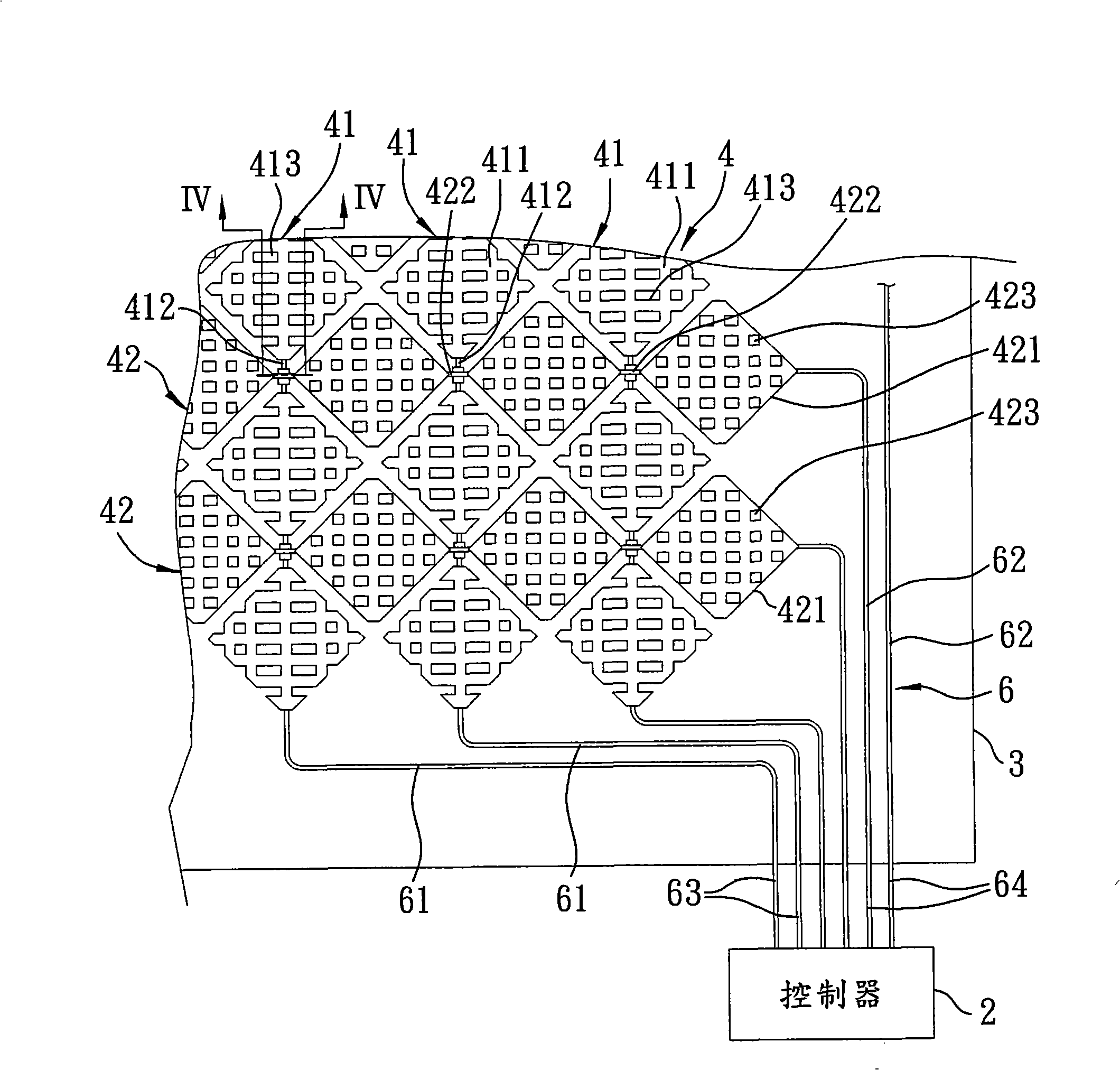
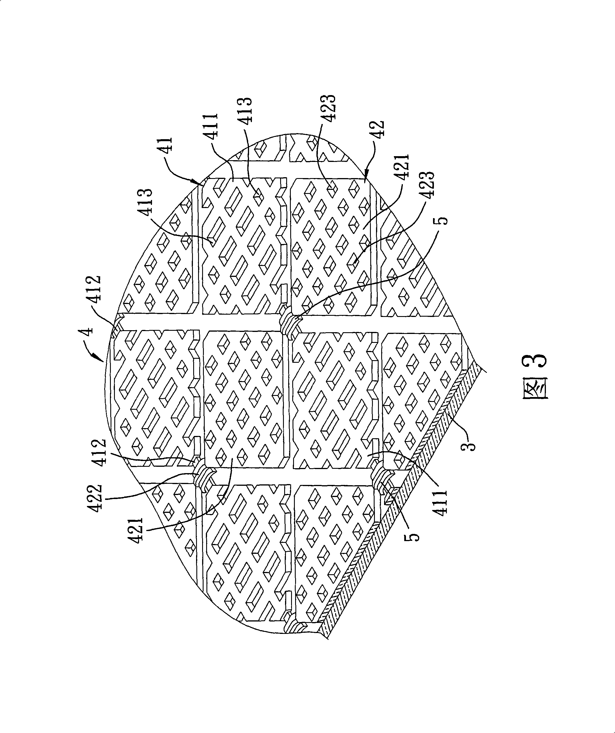
[0014] like figure 2 3 and 4, the preferred embodiment of the transparent touch panel device of the present invention is assembled on the screen (not shown) of a general electronic device, and a controller 2 detects the contact of the user's touch The touch panel device includes a horizontal and transparent substrate 3, a capacitive touch unit 4 located on the top surface of the substrate 3 and made of a transparent material, a lead unit 6 electrically connected to the touch unit, and A protective film unit 7 covering the top surface of the capacitive touch unit 4 . In this embodiment, the transparent touch panel device is installed on the screen as an example for illustration, but in actual implementation, it can also be used as a mouse pad of a notebook computer. Therefore, the scope of implementation does not depend on whether the substrate 3 and the touch ...


PUM


Abstract

The invention discloses a transparent contact control panel device, comprising a horizontal substrate and a capacitor-typed contact control unit. The capacitor-typed touch control unit is provided with a plurality of first electrode plates which are arranged on the top surface of the substrate in a matrix way, a plurality of second electrode plates which are arranged on the top surface of the substrate in the matrix way and intermittently arranged between the first electrode plates in an interlacing way, a plurality of first conductive wires which extend along straight direction and are electrically connected with the adjacent first electrode plates respectively, a plurality of second conductive wires which extend transversely, are electrically connected with the adjacent second electrode plates and crossly arranged with the first conductive wires in a spanning way, and a plurality of separation sheets which are respectively arranged at the crossing positions of the first conductive wires and the second conductive wires and laminated between the first conductive wires and the second conductive wires. By the separation sheets spliced at the crossing positions of the first conductive wires and the second conductive wires and by completely forming the capacitor-typed touch control element on the top surface of the substrate, the structure of the capacitor-typed touch control element can be greatly simplified, and disturbance caused by wire-beating in both surfaces can be avoided, thus improving the yield.

Description

technical field [0001] The present invention relates to a transparent touch panel device, in particular to a transparent touch panel device installed on an electronic product and used by a user to touch the electronic product with a charged object. Background technique [0002] In general daily life, touch panels are widely used in various electronic products, such as ATMs in financial institutions, navigation information systems in department stores, or PDAs and notebook computers, and are detected according to them. The physical principles of touch points can be divided into three types of touch panels: resistive, capacitive and wave. Various touch panels with different detection principles have different advantages and disadvantages. [0003] FIG. 1 shows the structure of a current general capacitive touch panel device. The capacitive touch panel device has a horizontal substrate 11 , a first electrode unit 12 located on the top surface of the substrate 11 , and a first e...

Claims


Application Information

Patent Timeline
Patent Type & Authority Applications(China)
IPC IPC(8): G06F3/044
Inventor 张玉辉
Owner 触控科技有限公司
Learn More