Eureka AIR delivers breakthrough ideas for toughest innovation challenges, trusted by R&D personnel around the world.

STATCOM controlling method

A control method and current control technology, applied in power network operating system integration, information technology support system, climate sustainability, etc. The effect of low loss and improved utilization

Inactive Publication Date: 2008-12-31
TONGJI UNIV
View PDF0 Cites 6 Cited by
  • Summary
  • Abstract
  • Description
  • Claims
  • Application Information

AI Technical Summary

Problems solved by technology

The response speed of direct current control is fast, but the switching frequency of the switch is high, which is suitable for the control of STATCOM with small and medium power

Method used


Image

  • STATCOM controlling method
  • STATCOM controlling method
  • STATCOM controlling method

Examples


Embodiment Construction

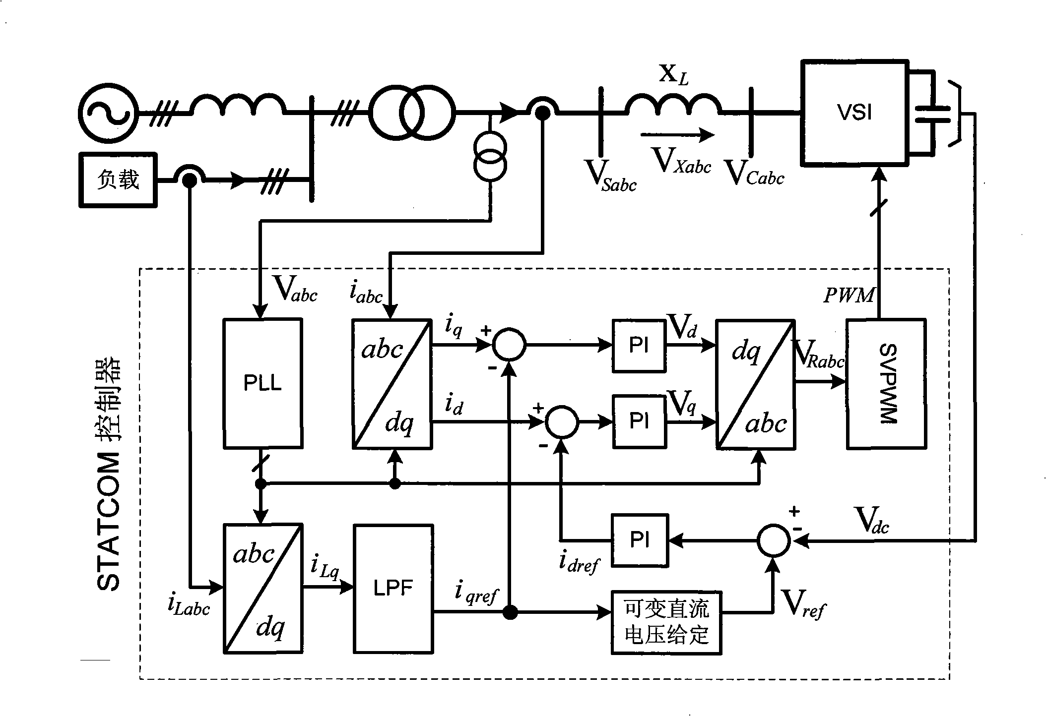
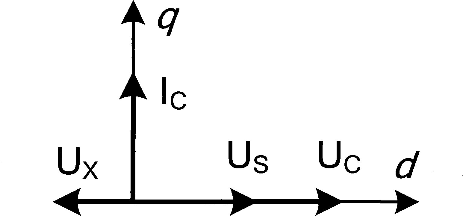
[0025] image 3 and Figure 4 They are the phasor diagrams of the system when the compensation current is leading and the compensation current is lagging, respectively. In order to simplify the description, the active current exchange between STATCOM and the system is not considered. where I C , U S , U C , U X respectively i abc , V Sabc , V Cabc , V Xabc Phasor representation in dq coordinates.

[0026] image 3 is the phasor diagram of the system when the compensation current leads, at this time the compensation current I output by STATCOM C Leading supply voltage U S , the inductor voltage U X with supply voltage U S in the opposite direction. STATCOM output voltage U C size|U C |=|U S |+|U X |, then |U C |>|U S |, that is, the output voltage U C than the supply voltage U S big. while the output voltage U C is determined by the DC voltage in the STATCOM, so the STATCOM must use a higher DC voltage.

[0027] Figure 4 is the phasor diagram of the ...


PUM


Abstract

The invention discloses an STATCOM control method which adopts direct current to control the STATCOM, and the DC voltage adopted by the STATCOM is variable. The variable DC voltage is always kept to be equal to the DC voltage reference value; the DC voltage adopted by the STATCOM when the compensation current leads is larger than the DC voltage adopted by the STATCOM when the compensation current lags so that the STATCOM can achieve the rated compensation capacity. By adopting the control method of the invention, the switching loss of a power device and the harmonic component of the output current can be reduced by the change of the DC voltage so that the device has the advantages of fast response, high efficiency and low in-power grid harmonic current. In addition, the advantages are proved by the simulation and the experiment, and the control method of the invention can be applied to the control of STATCOMs with medium or small capacity.

Description

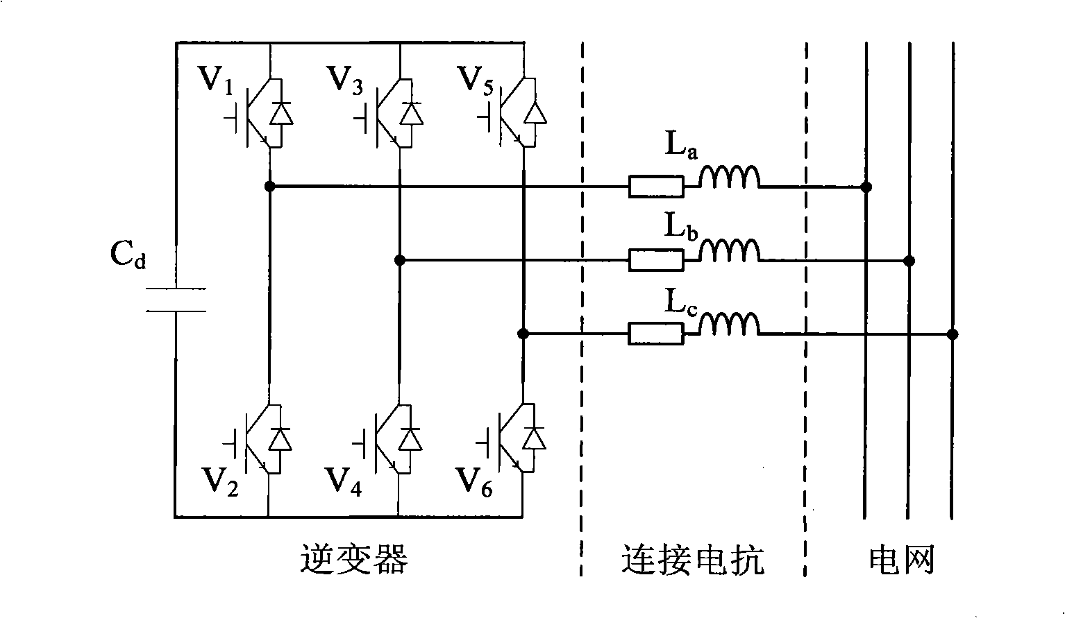
technical field [0001] The invention relates to a control method of a power electronic device, in particular to a STATCOM control method. Background technique [0002] STATACOM (Static Synchronous Compensator) is called static synchronous reactive power compensator, also known as active reactive power compensator or advanced reactive power generator. It uses power electronic devices to inject continuously adjustable leading or lagging reactive power into the grid. It is used to improve the power factor of the grid, stabilize the grid voltage, and reduce the loss of the grid. [0003] The schematic diagram of the main circuit principle of STATCOM is as follows: figure 1 As shown, its core is an inverter, V 1 , V 2 , V 3 , V 4 , V 5 and V 6 It is the power switching device of the inverter, and the DC side of the inverter has a capacitor C d , the AC side is connected by reactance L a , L b and L c Connected to the grid. [0004] At present, there are two control me...

Claims


Application Information

Patent Timeline
Patent Type & Authority Applications(China)
IPC IPC(8): H02J3/12H02J3/14H02J3/16H02J3/01
CPCY02B70/3225Y02E40/10Y02E40/30Y02E40/40Y04S20/222
Inventor 郭育华丁娜舒泽亮张昆仑
Owner TONGJI UNIV
Why Eureka
Eureka Blog
Learn More