Horizontal type rolling rotor compressor return air cooling structure

A rolling rotor and air-cooled technology, which is applied in the direction of machines/engines, liquid fuel engines, and rotary piston machines, can solve the problems of non-negligible rotor oil churning loss, insufficient oil supply, and low oil level at the oil suction pipe, etc., to achieve Effects of improving reliability, raising oil level, and improving motor efficiency

Inactive Publication Date: 2009-01-07
SHANGHAI HITACHI ELECTRICAL APPLIANCES CO LTD
View PDF0 Cites 5 Cited by
  • Summary
  • Abstract
  • Description
  • Claims
  • Application Information

AI Technical Summary

Problems solved by technology

Although this design can ensure the cooling of the motor, due to the pressure difference, the refrigerating machine oil accumulates in the motor cavity, wh

Method used


Image

  • Horizontal type rolling rotor compressor return air cooling structure
  • Horizontal type rolling rotor compressor return air cooling structure
  • Horizontal type rolling rotor compressor return air cooling structure

Examples


Embodiment

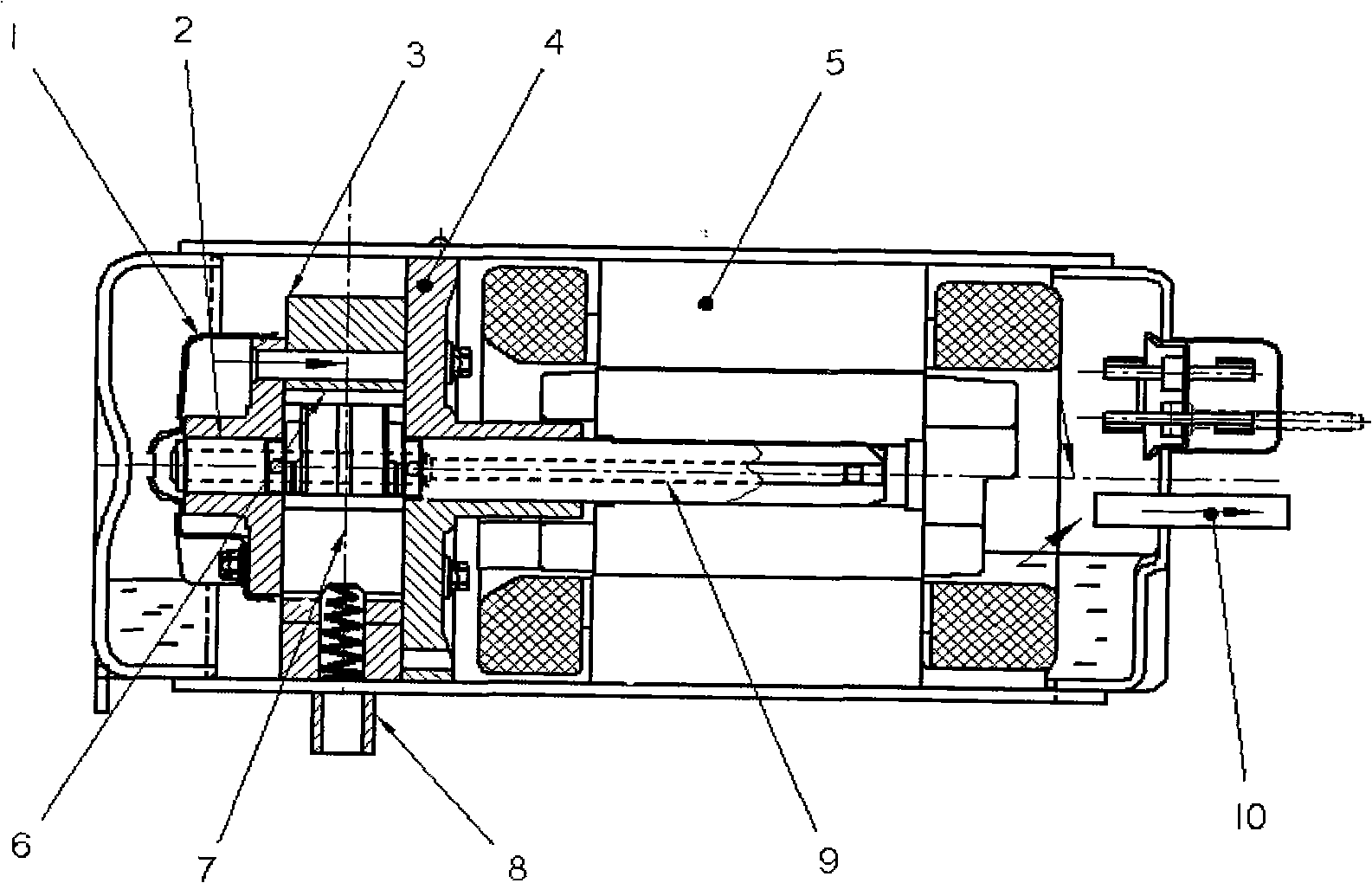
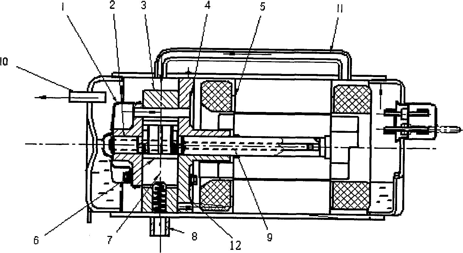
[0020] Such as Figure 2~3 As shown, a horizontal rolling rotor compressor return air cooling structure, the structure is as follows: parts 2 (lower cylinder head), 3 (cylinder), 4 (upper cylinder head) are assembled together by bolts to form the static part of the compression part Part 9 (crankshaft), 6 (piston) and 7 (vane) constitute the moving part, which is driven by 5 (motor) to rotate the crankshaft to complete the process of compressing the gas. 1 (lower muffler) is installed outside the lower exhaust to start To eliminate exhaust noise. 8 (intake pipe) and 10 (exhaust pipe) complete the gas input and output work, and the whole structure is sealed by the closed shell. 11 (air return pipe) acts as an exhaust guide, and is used to guide the exhaust to cool the motor and improve the height of the oil level on the side of the pump body.

[0021] With 4 (upper cylinder head) as the partition, the inside of the housing is divided into a compression chamber and a motor cham...


PUM


Abstract

The present invention relates to a return air cooling structure of a horizontal rolling rotor compressor, which comprises an upper cylinder cover, an air cylinder, a lower cylinder cover, an electric motor, a piston, blades, an air inlet pipe, a crankshaft, an exhaust pipe, a muffle as well as a return air pipe; wherein, the return air pipe, which can guide exhausted air to cool the electric motor and increase the level of the pump body side oil surface, is arranged on the end of the electric motor which is far from a pump body; the exhaust pipe is arranged on the pump body side; the exhausted air is exhausted into the cavity of the electric motor through a channel on the air cylinder and the upper cylinder cover, then flows back to a compressing cavity through the return air pipe and is finally exhausted through the exhaust pipe; therefore the exhausted air can directly cool the electric motor. Compared with the prior art, the return air cooling structure can reduce the temperature of the electric motor and increase the level of the oil surface of the compressing cavity, thus increasing the efficiency of the electric motor and greatly improving the reliability of the compressor.

Description

technical field [0001] The invention relates to a return air cooling structure of a horizontal rolling rotor compressor, in particular to a heat pump water heater which prevents the refrigerant on the condenser side from migrating to the inside of the evaporator and the compressor. Background technique [0002] Generally speaking, as a machine for compressing fluid, a compressor is composed of a closed container, a motor and a compressor. The airtight container has a certain internal space; the motor component is installed in the airtight container to generate driving force; the compressor compresses the gas through the driving force of the motor. [0003] According to the type of installation, the compressor is divided into two types: horizontal and vertical. Usually, the axis of the electric part and compression part of the horizontal compressor is set parallel to the installation base of the horizontal compressor. If the vertical compressor If the machine is directly cha...

Claims


Application Information

Patent Timeline
IPC IPC(8): F04C18/356F04C29/04F04C29/12F04C29/06
Inventor 周易丁洪亮蔡俊卿
Owner SHANGHAI HITACHI ELECTRICAL APPLIANCES CO LTD
Why Eureka
Try Eureka