Pressure release device for oil well

A decompression device and oil well technology, which is applied to components of pumping devices for elastic fluids, wellbore/well components, and production fluids, etc., which can solve the problems of inconvenient maintenance, difficulty in adapting to oil wells with large and small gas volumes, and short service life And other issues

Inactive Publication Date: 2005-03-30
郑重
View PDF1 Cites 1 Cited by
  • Summary
  • Abstract
  • Description
  • Claims
  • Application Information

AI Technical Summary

Problems solved by technology

However, due to certain defects in its design, its service life is not very long, its maint

Method used


Image

  • Pressure release device for oil well
  • Pressure release device for oil well
  • Pressure release device for oil well

Examples


Embodiment Construction

[0010] The present invention will be further described below in conjunction with the embodiments and accompanying drawings.

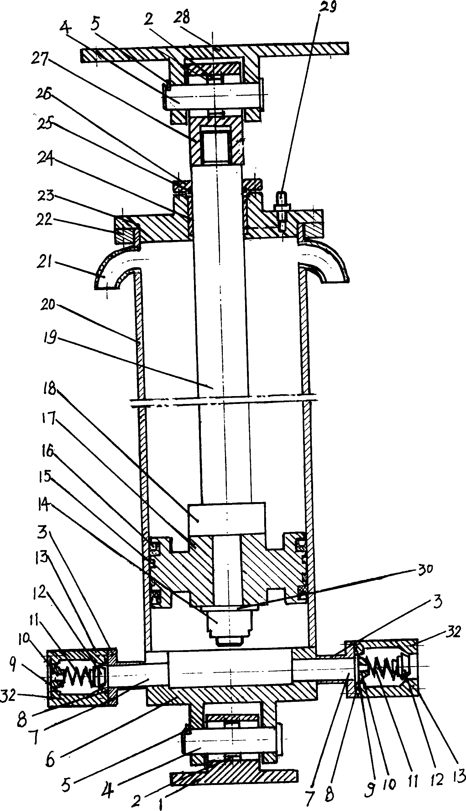
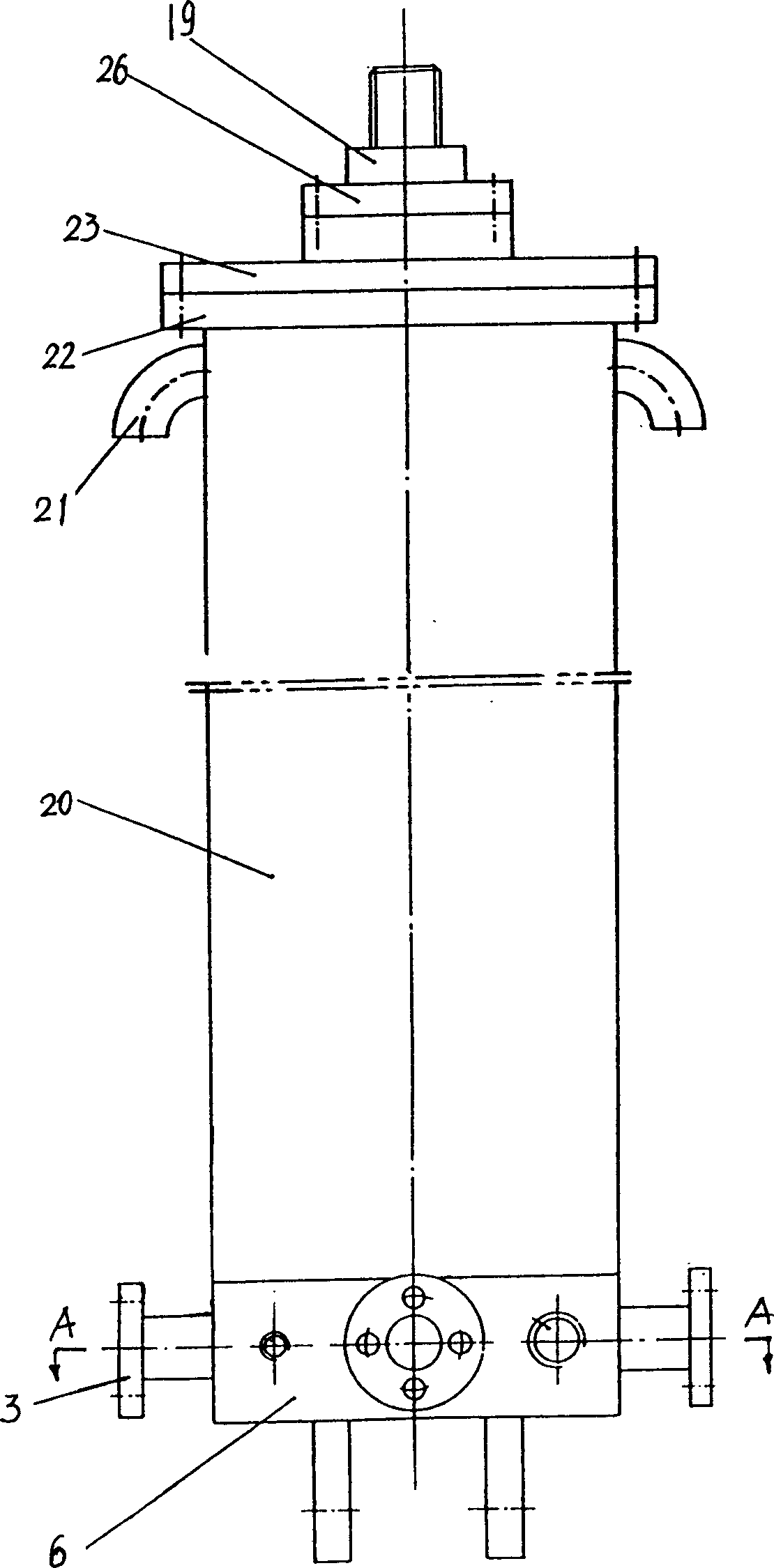
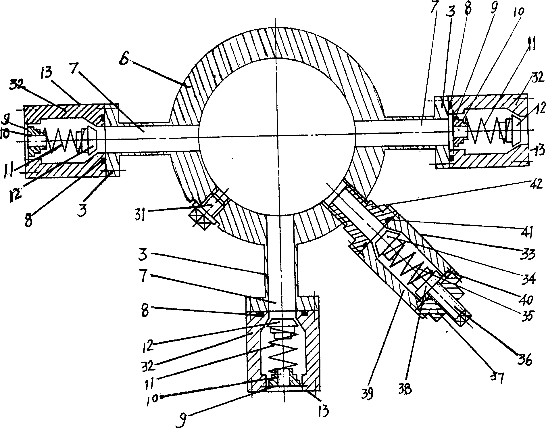
[0011] see Figure 1-Figure 3 , a kind of oil well decompression device, it is made of cylinder front cover 23, cylinder block 20, piston rod 19, piston 17, cylinder back cover 6, oil filling plug 29,31, has installation oil injection on the cover wall of cylinder front cover 23 The oil filling hole of the plug 29, the front end of the cylinder body 20 has an exhaust hole 21, the cylinder back cover 6 is equipped with a universal bearing 2 and a rear fixed plate 1, and the shaft pin 4 and the iron stopper 5 connect the rear fixed plate 1 with the cylinder back cover 6 Connected in one body, the front end of the piston rod 19 is threaded with the universal bearing sleeve 27, the universal bearing sleeve 27 is equipped with the universal bearing 2, the shaft pin 4 and the stopper 5 connect the front fixed plate 28 and the universal bearing sleeve 27 into ...


PUM


Abstract

The invention is a kind of decompression device of oil well, which is composed of cylinder front cover, cylinder body, piston rod, piston, cylinder back cover and oiling stopper.; the vent hole is opened on the front of the cylinder body; the cardan shaft and after fixing board are installed on the cylinder back cover; the after fixing board is fixed with the cardan bearing shell by axle pin and stop; three vent holes are opened on the side of the cylinder back cover and every vent hole is fixed unilateralism inverted valve through inverted valve flange; the oil feeding hole used for installing the oiling stopper is opened on the side of the cylinder back cover. It has the advantages of long useful life, changing and servicing easily, adapt able to the change of tolerance. It should be used with the walking beam type pumping unit.

Description

1. Technical field [0001] The invention relates to an oil well decompression device, in particular to an oil well decompression device used in conjunction with a conventional beam pumping unit. 2. Background technology [0002] In the process of oil production in the oil field, since the oil well contains a large amount of natural gas, a large amount of natural gas in the oil well will accumulate on the oil level of the oil well casing during the pumping unit’s round-trip pumping process, and the accumulated gas will affect the oil level. Negative pressure is generated, which reduces the pumping effect of the pumping unit. The way to solve this kind of problem in the oil field is usually to manually open the exhaust valve at the wellhead of the oil well to discharge the natural gas into the surrounding air, which not only causes a lot of waste of natural gas, but also pollutes the surrounding environment. Manual timing discharge increases the labor inten...

Claims


Application Information

Patent Timeline
IPC IPC(8): E21B43/00F04B53/06
Inventor 郑重
Owner 郑重
Why Eureka
Try Eureka