
Two-position five-way changing-over valve and sprinkling control system using same

A spraying control system and a two-position five-way technology, applied in the hydraulic field, can solve problems such as rising maintenance costs, inconvenient control, and high costs, and achieve the effects of reducing maintenance costs, easy operation, and easy processing

Active Publication Date: 2009-01-07
CHINA FIRST HIGHWAY ENG
View PDF0 Cites 5 Cited by
  • Summary
  • Abstract
  • Description
  • Claims
  • Application Information

AI Technical Summary

Problems solved by technology

However, there are still many defects in the existing two-position five-way reversing valve: one is that it cannot meet the requirements of high-speed and large-flow spraying; the other is that the structure is complicated and difficult to process; the third is that it is inconvenient to control and difficult to operate; cause maintenance costs to rise
Therefore, the existing two-position five-way reversing valve is still not suitable for use on the multi-way spraying control system

Method used


Image

  • Two-position five-way changing-over valve and sprinkling control system using same
  • Two-position five-way changing-over valve and sprinkling control system using same
  • Two-position five-way changing-over valve and sprinkling control system using same

Examples


Embodiment Construction

[0023] The following will be described in detail in conjunction with the embodiments and accompanying drawings.

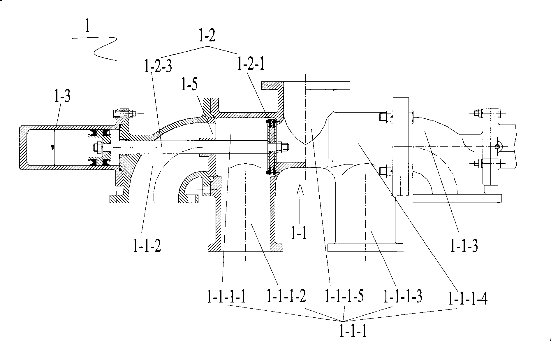
[0024] Please refer to figure 1 , which is a structural schematic diagram of a two-position five-way reversing valve of the present invention. The two-position five-way reversing valve 1 includes a valve body 1-1 and a valve core 1-2, wherein,

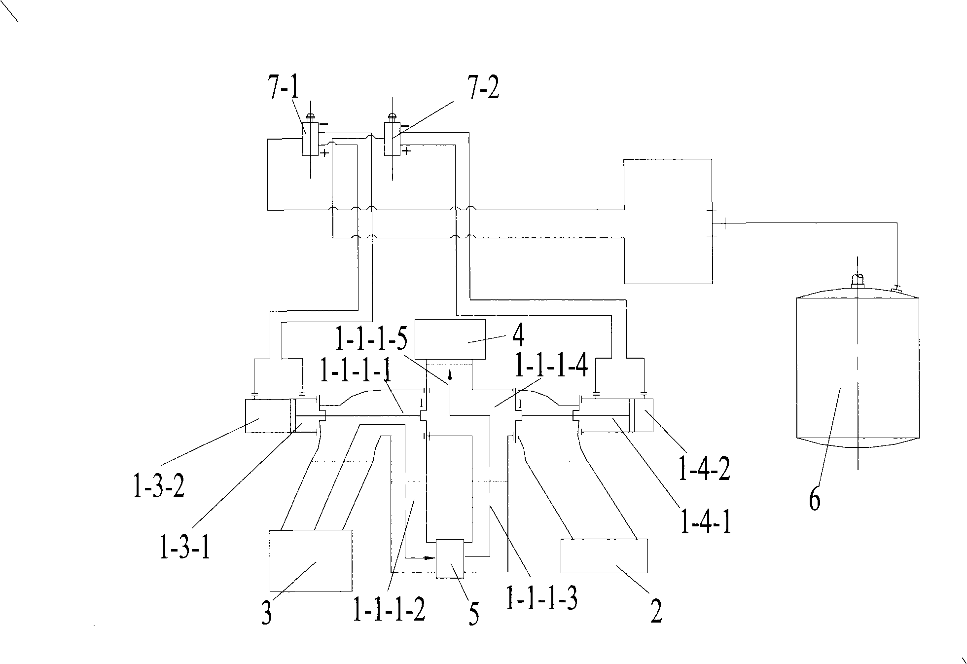
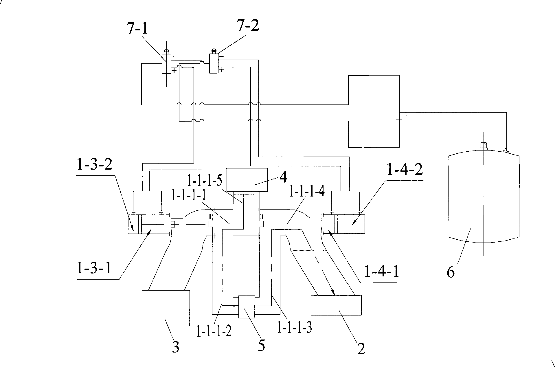
[0025] The valve body 1-1 includes a five-way pipe 1-1-1, which has five pipe sections distributed approximately in a star shape, wherein the first pipe section 1-1-1-1 of the five-way pipe, the fourth pipe section 1- 1-1-4 are respectively connected with the fifth pipe section 1-1-1-5, the second pipe section 1-1-1-2 is connected with the first pipe section 1-1-1-1, and the third pipe section 1-1-1 -3 is connected with the fourth pipe section 1-1-1-4; the first elbow 1-1-2, the second elbow 1-1-3, wherein, one end of the first elbow 1-1-2 is connected to the five The outlet of the first pipe section 1-1-1-1 of the throu...


PUM


Abstract

The present invention discloses a two-position five-way reversing valve. The valve body of the two-position five-way reversing valve comprises a five-way pipe, a first bent pipe and a second bent pipe; the five-way pipe is provided with five pipe sections which are distributed in the form of an approximate star, wherein, the first and the fourth pipe sections are respectively communicated with the fifth pipe section, the second pipe section is communicated with the first pipe, and the third pipe section is communicated with the fourth pipe section; one end of the first bent pipe and one end of the second bent pipe are respectively connected with the outlets of the first and the fourth pipe sections of the five-way pipe. The valve core of the two-position five-way reversing valve comprises a first sealing valve, a second sealing valve, a first link rod and a second link rod; wherein, the first and the second sealing valves are respectively arranged in the first and the fourth pipe sections of the five-way pipe; the first and the second sealing valves are respectively assembled on one end of the first link rod and one end of the second link rod, and the other ends of the first and the second link rods respectively penetrate the first and the second bent pipes and are connected with the output ends of a first manipulator and a second manipulator used to push the valve core to shift relative to the valve body. The two-position five-way reversing valve, which has the advantages of simple structure, convenient control and low cost, can satisfy the requirement on high-speed and large-flow multi-path spraying. On the basis of the two-position five-way reversing valve, the present invention also discloses a spraying control system using the two-position five-way reversing valve, which has two independent spraying paths.

Description

technical field [0001] The invention relates to the field of hydraulic technology, in particular to a two-position five-way reversing valve and a spraying control system using the two-position five-way reversing valve. Background technique [0002] The general spraying control system mostly uses two-position three-way reversing valve, but the two-position three-way reversing valve can only simply change the flow direction of the liquid, but cannot select the spraying channel. This is because: two-position three-way reversing The valve has only three outlets, and it can be connected to three sets of liquid devices at most; if there are two sets of liquid taking devices, one set of liquid supply devices is used; or, if there are two sets of liquid supply devices, one set of liquid taking devices is used. Therefore, due to the characteristic of the two-position three-way reversing valve, the existing spraying control system cannot meet the requirements of multi-way spraying. ...

Claims


Application Information

Patent Timeline
IPC IPC(8): F16K11/044F16K27/00F16K31/122B05B9/04
Inventor 李立红赵宾新
Owner CHINA FIRST HIGHWAY ENG
Learn More