Plane sliding window

A sliding window and plane technology, which is applied in the direction of the arrangement of the wings and leaves, can solve the problems of the bottom edge of the window frame being worn, poor sealing, and affecting the appearance, and achieve the effect of good sealing performance, good stability, and beautiful appearance

Inactive Publication Date: 2009-01-14
黄汉帆 +1
View PDF0 Cites 7 Cited by
  • Summary
  • Abstract
  • Description
  • Claims
  • Application Information

AI Technical Summary

Problems solved by technology

However, most of the current sliding windows are provided with two rails on the window frame for the two sashes to be pushed and pulled to realize opening and closing. , which widens the cross-sectional width of the window frame and consumes a large amount of aluminum or plastic materials
The utility model patent "Plane Airtight Sliding Window "Patent No. 02234421"" discloses a plane airtight sliding window whose sash is divided into a reversible sliding sash and a linear sliding sash, which overcomes the fact that the sash is not on the same plane when the traditional sliding window is closed, which affects the appearance , poor sealing and other problems
However, when the two sashes of this window are pushed and pulled, two parallel tracks still need to be set on the window frame, and the window frame still needs to have sufficient width, which cannot save materials.
The utility model patent "Monorail Horizontal Sliding Window "Patent No. 92216873" discloses another kind of sliding window, which overcomes the problems that the sash is not on the same plane when the traditional sliding window is closed, affects the appearance, and has poor sealing performance. Compared with the use of double rails, it can be reduced by half, which can save a lot of materials, etc.
But this patent still has the following deficiencies: 1. The other axis of the zigzag crankshaft connected to the linkage groove of the window is directly inserted into the hole on the bottom surface of the window frame. The bottom edge of the window frame is worn; 2. The linkage groove of the window is movable and can rotate with the crankshaft. During the sliding process of the movable window sash, it is easy to be stuck by the pulley at the bottom of the window sash. In addition, the length of the linkage groove is limited and cannot Extending to the fixed window sash, when the movable window slides to one end of the fixed sash, the movable window is only suspended by sliding shoes, and the bottom is not supported and is not stable enough; 3. The patented fixed window cannot slide, which is inconvenient to use; 4. The patent is only applicable to The window type with fixed transom cannot be used for the window type without fixed transom because there is no slideway for sliding shoes; 5. It is inconvenient to install screen windows with this structure

Method used


Image

  • Plane sliding window
  • Plane sliding window
  • Plane sliding window

Examples


Embodiment 1

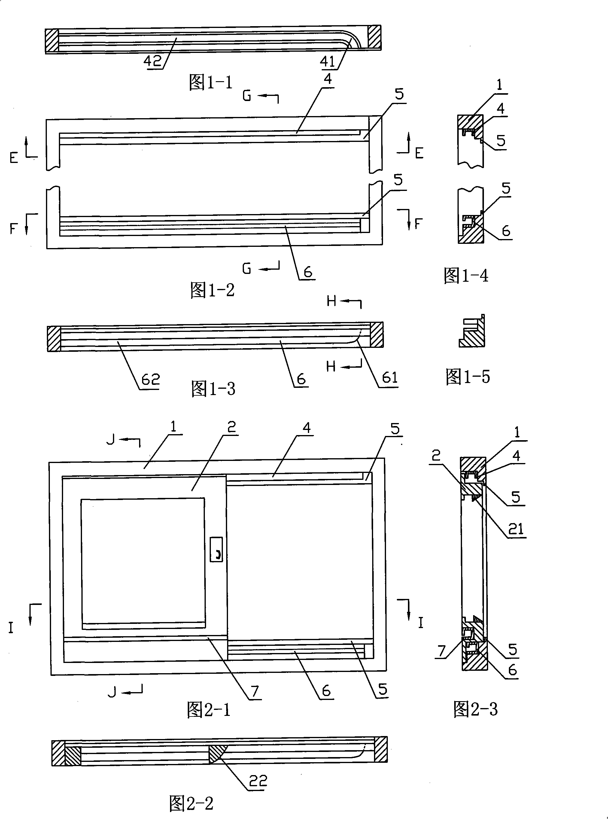
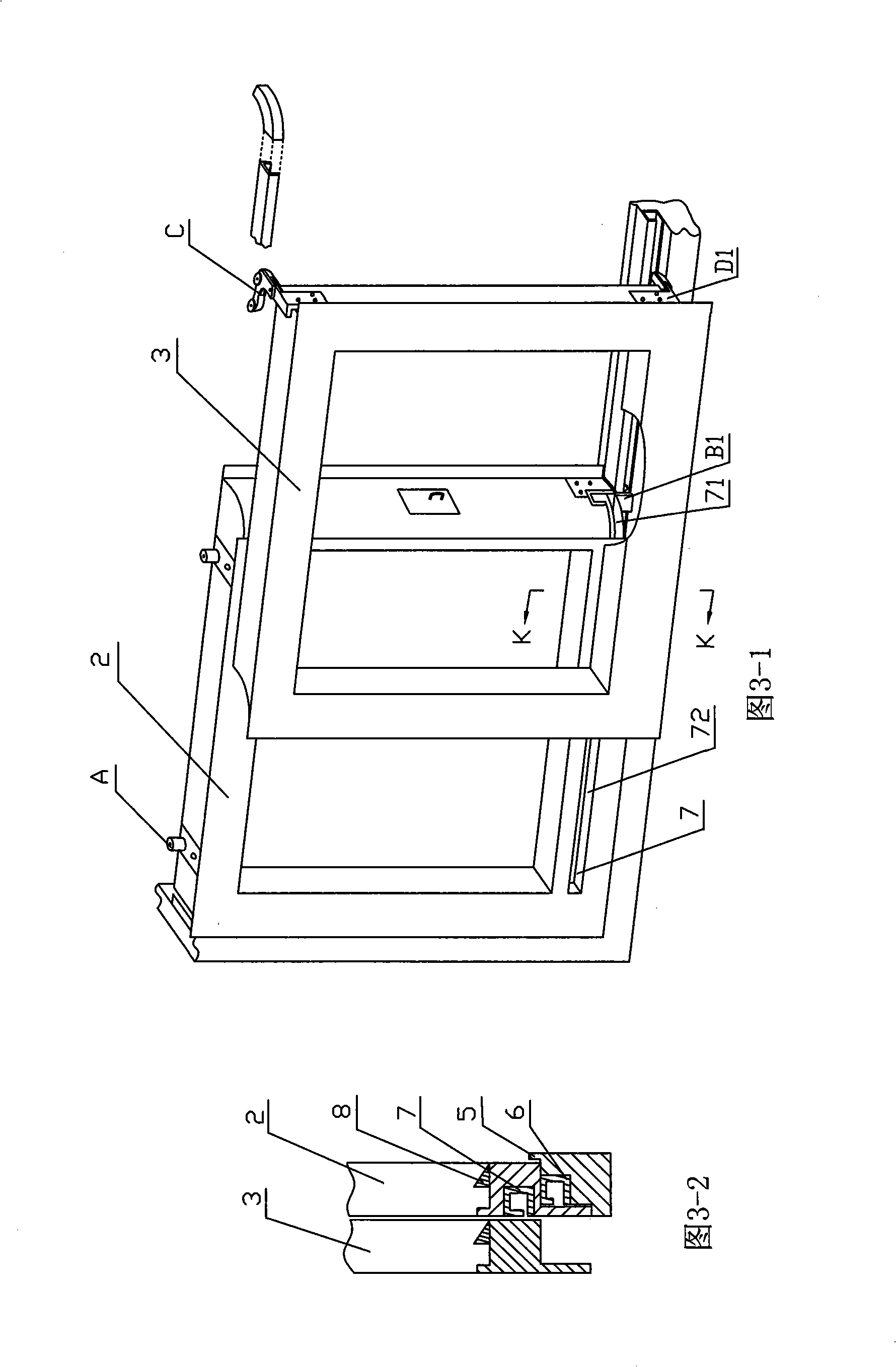
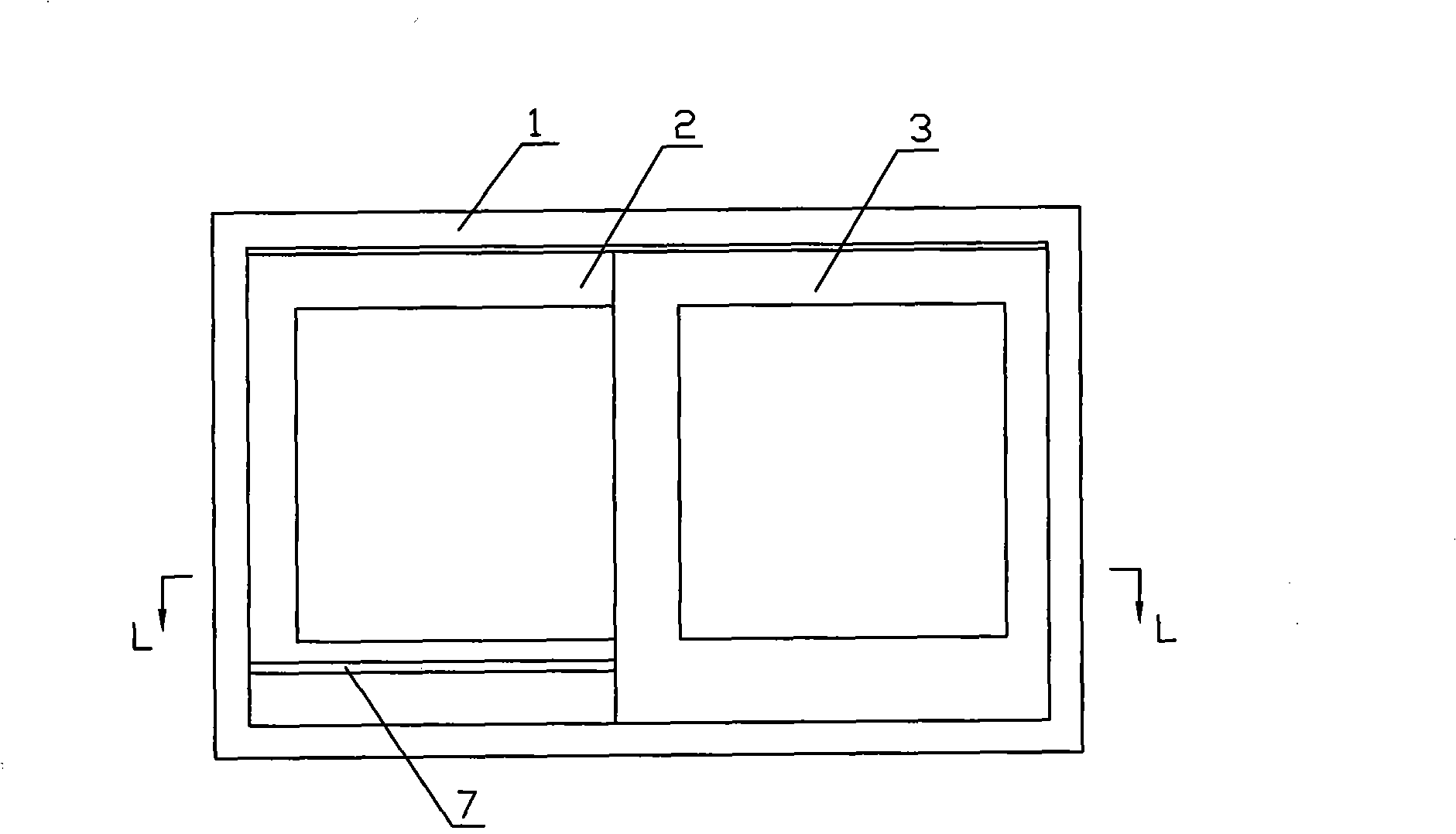
[0051] A plane sliding window, comprising a window frame and a window sash, the upper and lower beams of the window frame are respectively provided with upper and lower rails 4, 6, and the upper rail 4 and the lower rail 6 respectively have arc segments 41, 61 at the end close to the installation of the sliding sliding window sash, The end of the arc segment is about 3cm away from the vertical edge of the window frame (see Figure 1-1 and Figure 1-3). The window sash includes direct push sash 2 and translational push-pull sash 3. When the window is closed, the direct push sash and the translational push-pull sash On the same vertical plane, its butt end faces 22 and 32 are respectively circular arc surfaces (see Pic 4-1 , Figure 4-2 ), an auxiliary track 7 is arranged on the lower horizontal frame of the direct push window sash, and the auxiliary track extends to the arc end face 22 of the direct push window sash to form an arc segment 71, and a pulley A is installed on the to...

Embodiment 2

[0059] A flat sliding window, the basic structure of which is the same as above, the difference is that the cross-section of the lower rail 6 installed above the lower beam of the window frame is an inverted "∏" shape, the opening is upward, and the sliding assembly at the bottom of the sash is pushed directly at this time You only need to use ordinary pulleys, so the installation is relatively simple, but it brings some troubles to the cleaning of the track.

Embodiment 3

[0061] The utility model relates to a combined plane sliding window. It uses the plane sliding window described in Embodiment 1 of the present invention as a window unit, a balcony or other large windows made by combining multiple window units, and one or two sliding sliding windows on both sides of a direct pushing window sash can also be used. Arbitrarily assembled in the manner, the structure of each direct push sash, translational push-pull sash and the corresponding window frame, upper and lower tracks, and auxiliary track structures are the same as those in Embodiment 1, and will not be repeated here.

[0062] As a transformation of the embodiment of the present invention, the auxiliary track 7 on the lower frame can also be directly arranged on the lower frame of the direct push sash, that is, the auxiliary track 7 is a horizontal line opened on the lower frame of the direct push sash. The long groove in the direction, the long groove is extended to the circular arc end...


PUM


Abstract

Disclosed is a planar sliding window which comprises a window frame, a direct pushing window sash and a horizontal sliding window sash, a single upper rail and a single lower rail respectively provided with a circular arc section are respectively arranged on the upper beam and the lower beam of the window frame, when the window is closed, the direct pushing window sash and the horizontal sliding window sash are on the same vertical plane and the butt-jointed end surfaces thereof respectively adopt a circular arc surface, an auxiliary rail with one end provided with a circular arc section is arranged on the lower transversal frame of the direct pushing window sash, the cross section of the upper rail adopts an N shape, the cross sections of the lower rail and the auxiliary rail respectively adopt a quadrangle with one side opened, a pulley arranged at the top end of the direct pushing window sash slides on the straight line section of the upper rail, a pulley assembly arranged at the bottom end of the direct pushing window sash slides on the straight line section of the lower rail, the pulley assembly arranged at the top end of the horizontal sliding window sash and the pulley assembly arranged at one corner of the bottom end of the horizontal sliding window sash respectively slide on the straight line section and the corresponding circular arc section of the upper rail, and the pulley assembly arranged at the other corner of the bottom end of the horizontal sliding window sash only slides within the straight line section and the circular arc section of the auxiliary rail. The invention has the advantages that the appearance of the planar sliding window is artistic, the sliding is flexible, the operation is convenient, the applicable range is wide, the material is saved and the cost is low.

Description

Technical field: [0001] The invention relates to a house window, in particular to a plane sliding window. Background technique: [0002] At present, the opening methods of house windows generally include flat opening and push-pull. Since the sash of the push-pull window is located in the rail groove of the window frame, it can be pushed and pulled freely. The force of the sash is uniform, stable, and strong in wind resistance. Beautiful appearance and other advantages, so it is widely used, especially in high-rise buildings. However, most of the current sliding windows are provided with two rails on the window frame for the two sashes to be pushed and pulled to realize opening and closing. , and the cross-sectional width of the window frame is widened, consuming a large amount of aluminum or plastic materials. The utility model patent "Plane Airtight Sliding Window "Patent No. 02234421"" discloses a plane airtight sliding window whose sash is divided into a reversible slid...

Claims


Application Information

Patent Timeline
Patent Type & Authority Applications(China)
IPC IPC(8): E06B3/46
Inventor 黄汉帆
Owner 黄汉帆
Why Eureka
Try Eureka