Vane compressor or vacuum pump

A compressor and vane technology, applied in the field of vane compressors or vacuum pumps, can solve the problems of fast wear of compressors or vacuum pumps, poor sealing performance, low output pressure, etc., and achieve the effects of high pressure, not easy to wear, and high power

Inactive Publication Date: 2009-01-14
JDM JINGDA MASCH (NINGBO) CO LTD
View PDF0 Cites 23 Cited by
  • Summary
  • Abstract
  • Description
  • Claims
  • Application Information

AI Technical Summary

Problems solved by technology

This type of compressor or vacuum pump is sealed by a contact line between the blades and the cylinder body, so the sealing performance is poor, the output pressure is low, and there is a lot of friction between the blades, the rotor and the cylinder body during rotation, resulting in the compressor Or the overall wear of the vacuum pump is fast, the life is short, and the efficiency is low

Method used


Image

  • Vane compressor or vacuum pump
  • Vane compressor or vacuum pump
  • Vane compressor or vacuum pump

Examples


Embodiment Construction

[0034] The present invention will be further described in detail below in conjunction with the accompanying drawings and embodiments.

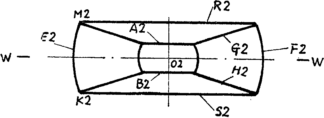
[0035] The structure of the present invention is shown in Figure 5, the rotor 2 is located at the center, the housing 1 is located at the outside, and the blades 3 are located on both sides of the rotor 2, and are placed in the hollow ring (guide groove) at the opposite corner of the housing 1, and are connected with the rotor 2 form an angle, the vane 3 is tangent to the side of the circular table of the rotor 2, the sealing strip 4 is located between the rotor 2 and the vane 3, the plane side of which is attached to the rotor 2, and the cylindrical side is attached to the vane 3, and the gasket The block 5 is located in the hollow circle at the opposite corner of the housing 1, just filling the void formed by the blade 3, the rotor 2 and the sealing strip 4.

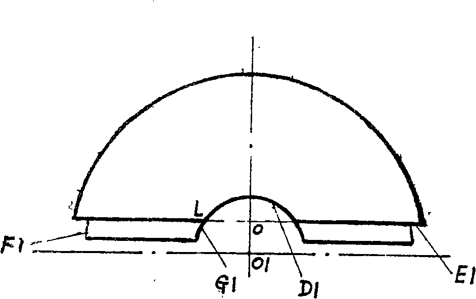
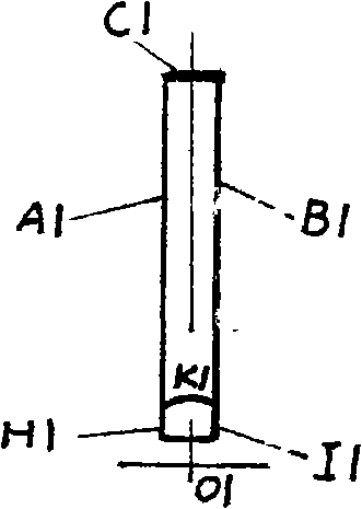
[0036] Figure 1a and Figure 1b Shown are the shapes of the blade 3 and the seal...


PUM


Abstract

The invention discloses a blade-typed compressor or vacuum pump which comprises a shell, a rotor, two same blades, four same sealing strips and two same cushion blocks, wherein, the rotor is positioned in the center, the shell is positioned in the exterior, the blades are positioned at two sides of the rotor, arranged in a hollow circular ring of the opposite angle of the shell to form an angle with the rotor, and tangent with the side of the cone of the rotor, the sealing strips are positioned between the rotor and the blades, one side of the plane of the sealing strip is jointed with the rotor, while one side of the cylindrical surface thereof is jointed with the blades, and the cushion blocks are positioned in the hollow circular ring of the opposite angle of the shell to just fill the opening formed by the blades, the rotor and the sealing strips. The invention has the advantages that: 1) all the sealing points are surface sealing, 2) the output volume is large, the pressure and efficiency are high, 3) the specific power is high, 4) the structure is compact and the processing is comparatively easy, and 5) the production cost is comparatively low.

Description

technical field [0001] The invention relates to a compressor or a vacuum pump, in particular to a vane compressor or a vacuum pump. Background technique [0002] The structure of the existing vane compressor or vacuum pump is that the rotor is eccentrically placed in the cylinder body, and the blades are placed in the rotor radially or at a certain angle to the rotor radius. When working, the rotor rotates at a high speed, and the blades are thrown out under the action of centrifugal force. It forms a sealed cavity with the cylinder block, and the volume changes when it rotates to generate pressure. The number of leaves is two or more. This type of compressor or vacuum pump is sealed by a contact line between the blades and the cylinder body, so the sealing performance is poor, the output pressure is low, and there is a lot of friction between the blades, the rotor and the cylinder body during rotation, causing the compressor Or the overall wear of the vacuum pump is fast,...

Claims


Application Information

Patent Timeline
Patent Type & Authority Applications(China)
IPC IPC(8): F04C18/356F04C25/00F04C29/00
Inventor 陈行
Owner JDM JINGDA MASCH (NINGBO) CO LTD
Why Eureka
Try Eureka