
Escapement for electric power line without bolt

A technology without bolts and spacers, applied in the installation of electrical components, cables, devices for maintaining the spacing between parallel conductors, etc., can solve the problems of complex spring bearing parts, no specific representation, inconvenient heights, etc., to relieve stress. Effect

Inactive Publication Date: 2009-01-14
FURUKAWA ELECTRIC POWER SYST
View PDF2 Cites 6 Cited by
  • Summary
  • Abstract
  • Description
  • Claims
  • Application Information

AI Technical Summary

Problems solved by technology

[0012] Since the conventional device of Patent Document 1 is configured and operated as described above, the deviation of the electric wire holding force is extremely small, and it is possible to confirm that a predetermined holding force has been applied after construction by removing the jacking screw, and there is no need for a torque wrench. There are many other advantages, but on the other hand, in the case of intersecting and engaging the T portion and the fork, in addition to the ratchet wrench used to remove the jacking screw, in order to intersect and engage the T bolt, use the jack The tightening screw exerts compressive force on the T-bolt shaft, so it cannot be crossed and engaged manually, and a special bifurcated tool is required, which is inconvenient for high places where the foothold is unstable.
[0013] The conventional device of Patent Document 2 solves the problem of Patent Document 1 and does not require a special tool, but on the other hand, the structure of the spring receiving part provided on the other end side of the T-bolt head to allow the T-bolt head to rotate freely It is a complicated mechanism, and in spacers for UHV power transmission lines that require a plurality of bolt-free electric wire gripping parts, there is a problem that the weight of the spacer as a whole increases and the cost increases
[0014] In addition, no matter in any of the above-mentioned patent documents, it only shows the structure of the bolt-free electric wire holding part, and does not specifically show that it is used to minimize the occurrence of radio, television, etc. The arrangement method (mechanism) of the boltless wire gripping part in the spacer frame for the radio wave interference generated by corona discharge and the corona discharge noise generated by the raindrops formed around the boltless wire gripping part in rainy days, In the conventional design, the weight of the boltless wire holding part is too heavy, and there is a common problem that it is not possible to provide a lightweight and inexpensive spacer for UHV transmission lines

Method used


Image

  • Escapement for electric power line without bolt
  • Escapement for electric power line without bolt
  • Escapement for electric power line without bolt

Examples


Embodiment Construction

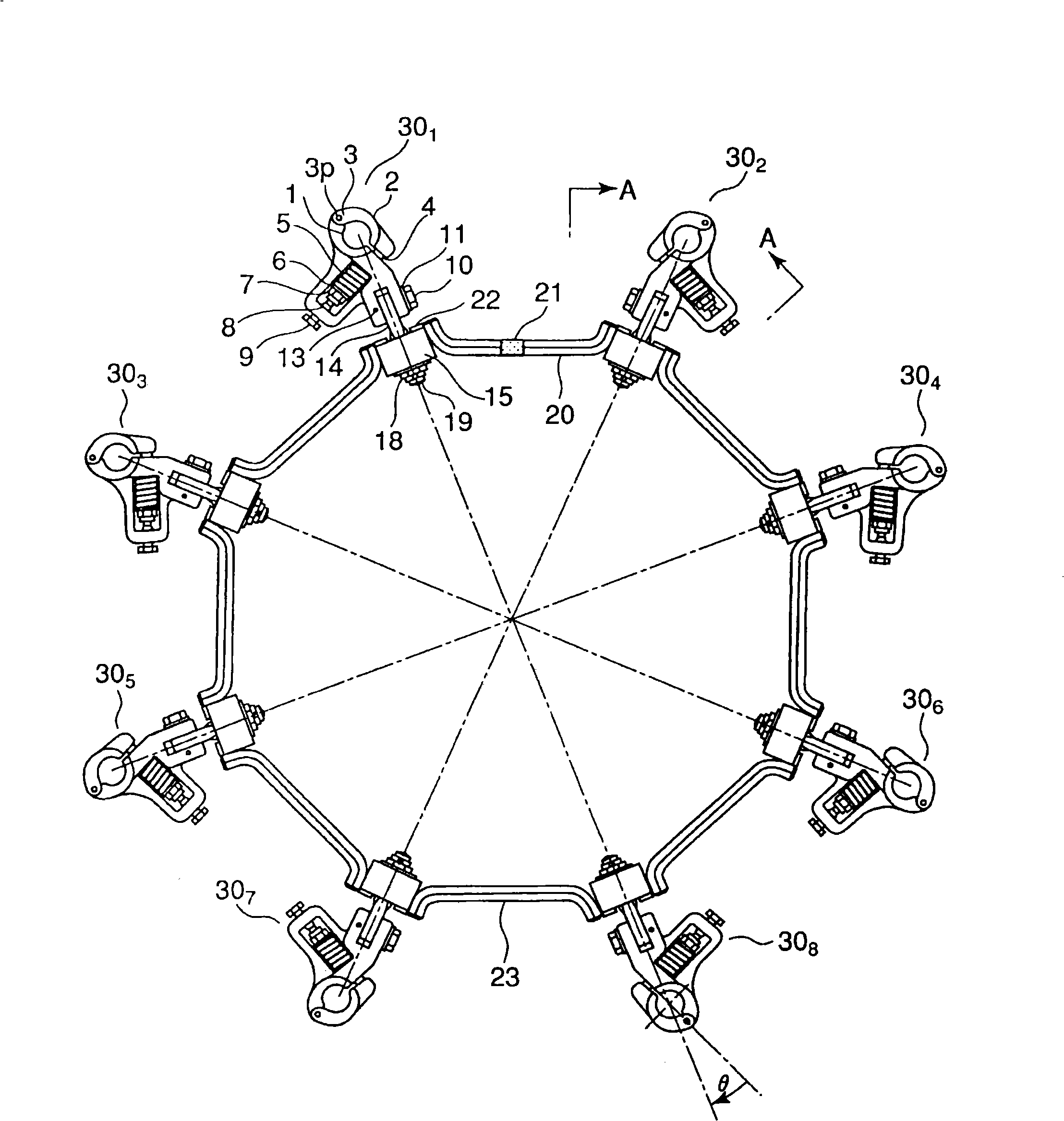
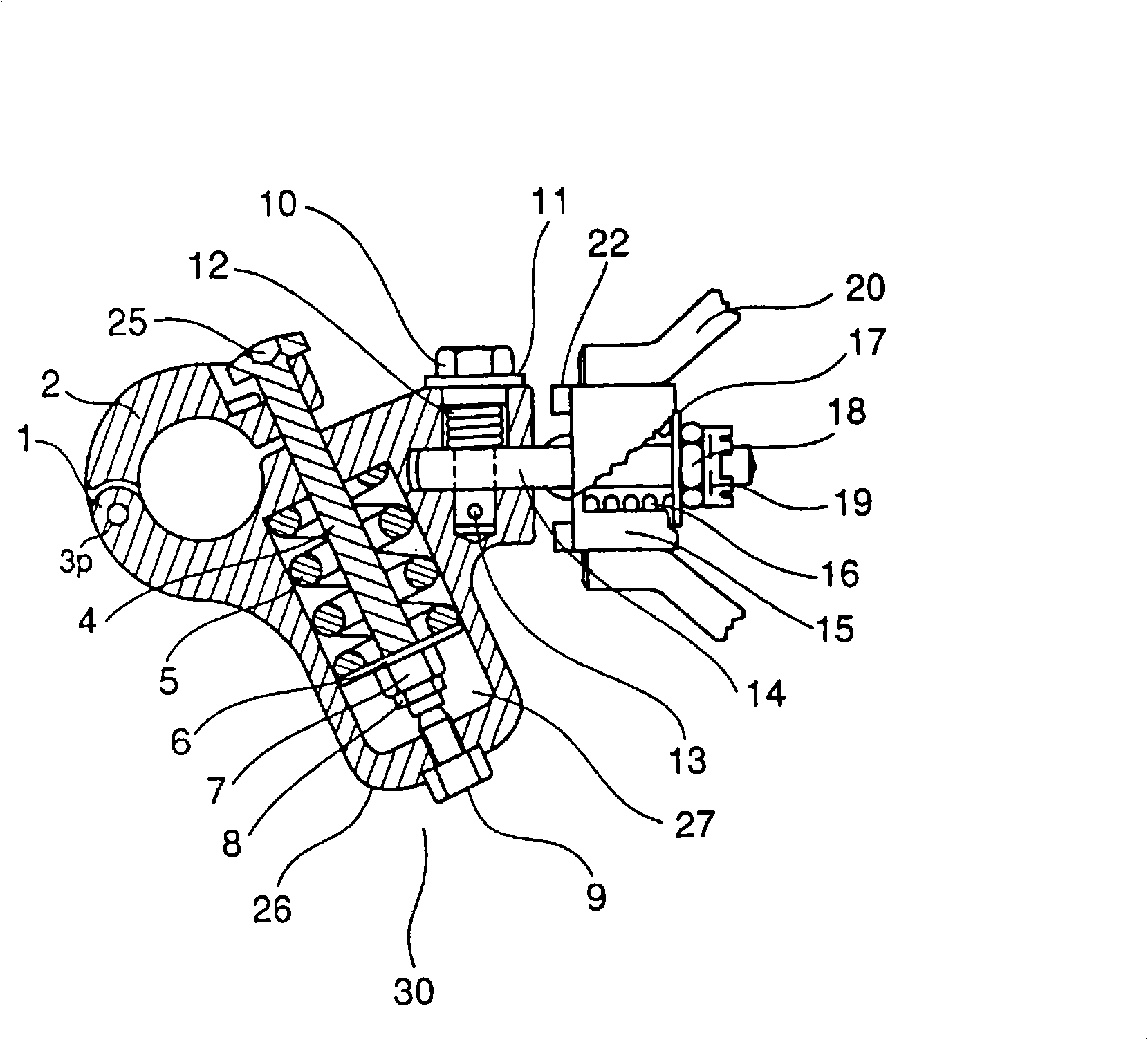
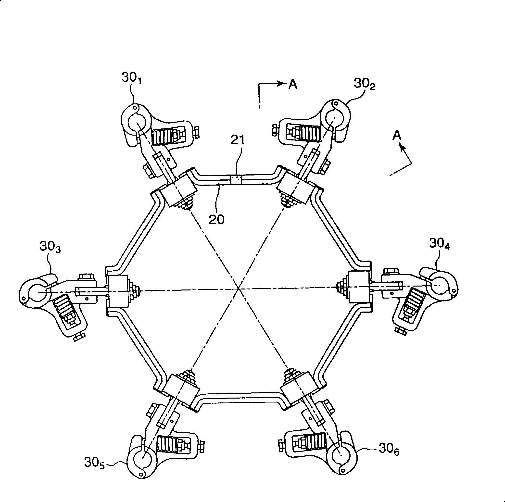
[0041] Below, refer to Figure 1 to Figure 8 An example of the present invention will be described.

[0042] figure 1 It is a front view of a boltless spacer for 8 conductors when the spacer of the present invention is applied to a UHV8 conductor transmission line.

[0043] figure 2 It is no bolt electric wire grip part 30 1 enlarged sectional view of the .

[0044] image 3 It is a front view of a 6-conductor boltless spacer for UHV power lines or UHV power lines.

[0045] In addition, in the following description, in the 8-conductor and 6-conductor boltless spacers, except that the mounting intervals of the former to the frame are 45° and the latter are mounted at 60° intervals, the boltless wire holding part and the boltless spacer to the frame The basic structure of connecting frames is the same, so the boltless spacer for 8 conductors will be explained.

[0046] First, the structure of the spacer of the present invention will be described by taking an 8-conductor...


PUM


Abstract

The invention provides a spacer frame configuration structure of bolt-free wire holding part and spacer for light-weight and cheap transmission line capable of largely reducing wave interference resulting from corona discharge of radio and TV or relatively high potential gradient such as UHV transmission line, and corona discharge noise resulting from water drip forming around bolt-free wire holding part in rain. The bolt-free wire holding part is axially symmetrical and mounted radially for performing gyratory motion corresponding to equilateral polygon, then connected with lead terminal, assembled on chamber; the gyration-proof block for keeping regular assembling posture of bolt-free wire holding part is oppositely disposed at two positions of outer plane, the wire clamp connector of bolt-free wire holding part changes its position in about + / - theta degree from multi-conductor symmetrical axis of maximum potential gradient for positioning bolt-free spacer suitable for UHV transmission line.

Description

technical field [0001] The present invention relates to a boltless spacer for multi-conductor electric wires, and more specifically, relates to a regular polygon formed by electric wires with 6 to 10 conductors constituting one phase, suitable for direct current or alternating current ultra-high voltage (UHV) ) The structure of the multi-conductor boltless spacer used for power transmission lines. Background technique [0002] As such a conventional bolt-free electric wire gripping portion, there is, for example, the patent document 1. Figure 8 ~ Figure 1 0 and Patent Document 2 Figure 1 ~ Figure 3 the structure described. [0003] [Patent Document 1] Japanese Publication No. 07-056572 [0004] [Patent Document 2] Japanese Patent Application Laid-Open No. 08-228422 [0005] In Patent Document 1 Figure 1 ~ Figure 1 In 1, reference numeral 1 is the main body of the electric wire holding part without bolts, and the weight 2 is rotatably attached by the pin 3, and the ele...

Claims


Application Information

Patent Timeline
IPC IPC(8): H02G7/12H02G7/00
Inventor 宗像武男板仓康博
Owner FURUKAWA ELECTRIC POWER SYST
Learn More