Intelligentized battery charge control circuit

A control circuit and battery charging technology, which is applied in the direction of secondary battery charging/discharging, battery circuit devices, circuit devices, etc., can solve problems such as the lifespan of rechargeable batteries, the hidden dangers of alarm work, and the inability to detect battery power supply circuits, etc., to achieve reduction Charging time, prolonging the charging time, and ensuring the effect of normal work

Inactive Publication Date: 2009-01-14
天津市中天峰电器有限公司
View PDF0 Cites 6 Cited by
  • Summary
  • Abstract
  • Description
  • Claims
  • Application Information

AI Technical Summary

Problems solved by technology

The battery in the existing alarm generally adopts two kinds of batteries: one is to use dry battery, the power circuit of this alarm is simple, the disadvantage is that the dry battery needs to be replaced frequently, if the battery is not replaced in time, the alarm will not work normally when the power is cut off Another kind is to adopt rechargeable battery, utilize its internal control circuit to charge rechargeable battery, but the following problems generally exist in existing control circuit: (1). The charging control circuit design is unreasonable, and the charging circuit cannot The current state intelligently controls charging, and the charging control circuit always charges the rechargeable battery, which makes the rechargeable battery in an overcharged state, resulting in a decrease in the life of the rechargeable battery; (2). The charging control circuit cannot detect whether the charging circuit is normal, and cannot detect charging early Whether there is a fault in the circuit, which makes the alarm work hidden; (3). The control circuit cannot detect whether there is a fault in the battery power supply circuit. Once there is a problem in the battery power supply circuit, the alarm will not work normally when the power is cut off.

Method used


Image

  • Intelligentized battery charge control circuit

Examples


Embodiment Construction

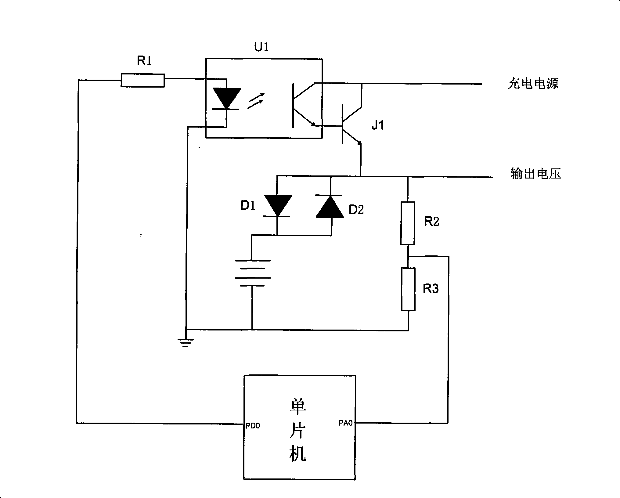
[0011] Embodiments of the present invention will be described in further detail below in conjunction with the accompanying drawings.

[0012] Such as figure 1 As shown, the intelligent battery charging control circuit is composed of a single-chip microcomputer and a control circuit. The single-chip microcomputer has a plurality of I / O interfaces with A / D conversion functions. The single-chip microcomputer used in this embodiment is an ATMEL16 with an A / D conversion function interface. Single-chip microcomputer, the single-chip microcomputer uses two I / O interfaces: one port is an input interface with A / D conversion function, that is, the voltage detection port PAO used to detect the voltage detection endpoint, and the other is an output port, which is used to control the circuit. Charge control port PDO that provides pulse signal to control charging time. The charging control port PDO and the voltage detection port PAO of the microcontroller are connected to the control circu...


PUM


Abstract

The invention relates to an intelligent battery charging control circuit in a controller. The main technical characteristics is that the charging control port of a single chip microcomputer sequentially connects to a resistance R1, an optical coupler U1 and a charging triode J1, the collector of the charging triode J1 is connected to the positive electrode of a charge power supply, the emitter of the charging triode J1 is respectively connected to the positive electrode of a diode, the negative electrode of the diode and one end of a resistance R2, the positive electrode and negative electrode of the diode are connected with the positive electrode of the charge power supply, the other end of the resistance R2 as voltage detection endpoint is connected to the voltage detection port and connected with one end of a resistance R3. The intelligent battery charging control circuit of the invention can detect voltage for the detection endpoint through the voltage detection port of the single chip microcomputer, output impulse with certain width through the charging control port of the single chip microcomputer according to the high/low of voltage, cooperate the charge power supply to charge the battery, further detect fault for the charging circuit and power supply circuit and alarm.

Description

technical field [0001] The invention belongs to a battery charging control circuit, in particular to an intelligent battery charging control circuit. Background technique [0002] With the continuous reduction of the price of single-chip microcomputers, more and more small electronic devices now use intelligent control circuits with single-chip microcomputers as the core, and some special electronic devices such as alarms not only require intelligent control, but also require alarms. It should also keep working during a power outage. Therefore, this type of alarm needs to have two modes of AC power supply and battery power supply at the same time, so as to ensure that in the case of a power failure, the battery power supply mode can still enable the alarm to continue to work. The battery in the existing alarm generally adopts two kinds of batteries: one is to use dry battery, the power circuit of this alarm is simple, the disadvantage is that the dry battery needs to be rep...

Claims


Application Information

Patent Timeline
Patent Type & Authority Applications(China)
IPC IPC(8): H02J7/00H01M10/44
CPCY02E60/10
Inventor 王毅
Owner 天津市中天峰电器有限公司
Why Eureka
Try Eureka