

Moving coil type micro-mechanical electromagnetic vibration energy acquisition device based on upconversion
An energy harvester and moving coil miniaturized technology, applied in the direction of electromechanical devices, electrical components, etc., can solve the problems of adjusting the internal damping force of the structure, limiting the induced electromotive force of the coil, changing the stiffness of the cantilever beam, etc., and achieving high frequency adaptability and high output Voltage and output power, the effect of simplifying process steps
- Summary
- Abstract
- Description
- Claims
- Application Information
AI Technical Summary
Problems solved by technology
Method used
Image

Examples
Embodiment 1
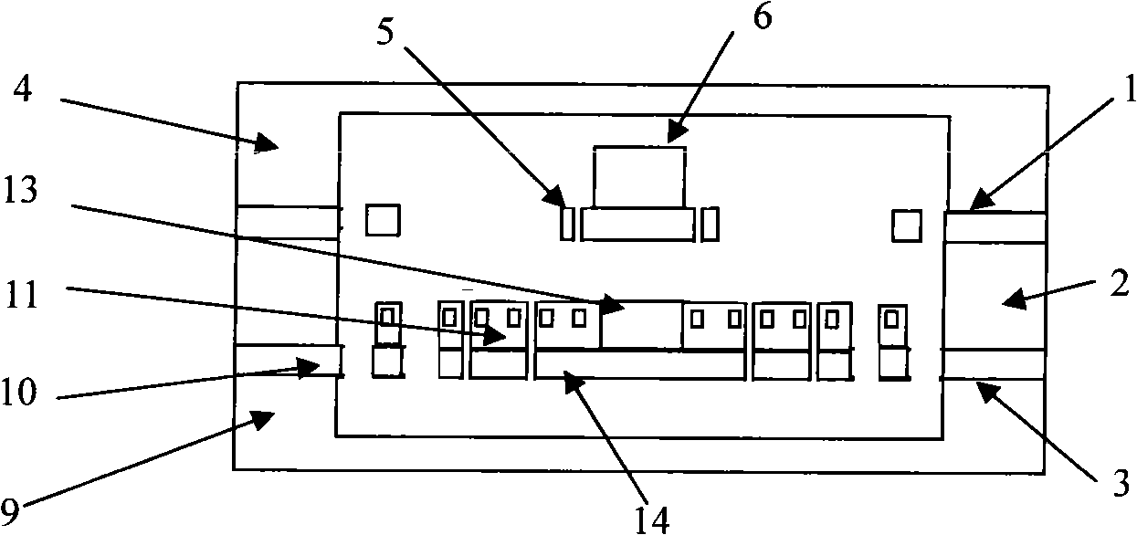
[0034] This embodiment is mainly aimed at the case where the external vibration frequency is lower than 50 Hz. Such as figure 1 As shown, this embodiment includes: an upper vibration pickup platform 1 , a gasket 2 and a lower vibration pickup platform 3 . The gasket 2 is located between the upper vibration pickup platform 1 and the lower vibration pickup platform 3 .
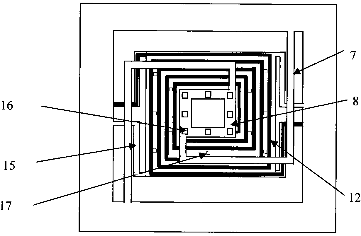
[0035] Such as figure 1 , 2 As shown, the upper vibration pickup table 1 includes: a top cover 4 , a metal planar spring 5 and a permanent magnet 6 . There is a pit in the center of the top cover 4, and the metal planar spring 5 is fixed on the edge of the pit in the top cover 4, including a central metal platform 8 and two cantilever beams 7 around it. The permanent magnet 6 is located on the metal platform 8 directly above the vibration pickup table 3 at the lower layer.
[0036] The pits on the top cover 4 have a depth of 200 microns to 400 microns, and a side length of 3 mm to 5 mm. It can be made of m...
Embodiment 2
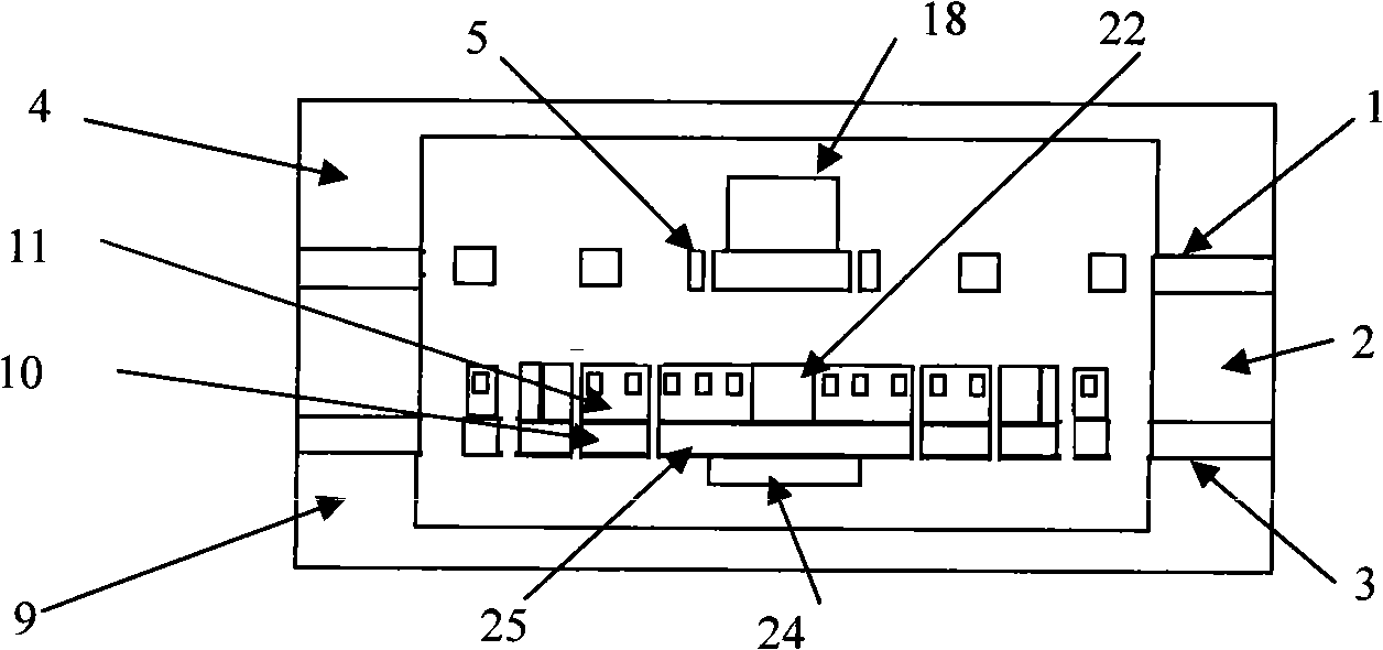
[0052] This embodiment is mainly aimed at the situation that the external vibration frequency is higher than 50 Hz and lower than 200 Hz. Such as image 3 As shown, this embodiment includes: an upper vibration pickup platform 1 , a gasket 2 and a lower vibration pickup platform 3 . The gasket 2 is located between the upper vibration pickup platform 1 and the lower vibration pickup platform 3 .
[0053] Such as image 3 , 4 As shown, the upper vibration pickup table 1 includes: a top cover 4 , a metal planar spring 5 and a permanent magnet 18 . There is a pit in the center of the top cover 4, and the metal plane spring 5 is fixed on the edge of the pit in the top cover 4, including a central metal platform 20 and four cantilever beams 19 around it. The permanent magnet 18 is located on the metal platform 20 , directly above the vibration pickup table 3 at the lower layer.
[0054] The pits on the top cover 4 have a depth of 200 microns to 400 microns, and a side length of ...
PUM
| Property | Measurement | Unit |
|---|---|---|
| Thickness | aaaaa | aaaaa |
| Depth | aaaaa | aaaaa |
| Thickness | aaaaa | aaaaa |
Abstract
Description
Claims
Application Information