
Device for rotationally locking the supporting roll balanced architecture of roll stands

A technology of rolling mill stand and balance cylinder, which is applied in the direction of metal rolling mill stand, metal rolling stand, metal rolling, etc., can solve the problems of non-compliance, etc., and achieve the effect of less maintenance cost

Active Publication Date: 2009-01-14
SMS DEMAG AG
View PDF2 Cites 4 Cited by
  • Summary
  • Abstract
  • Description
  • Claims
  • Application Information

AI Technical Summary

Problems solved by technology

This means that in the other two cases there are huge safety deficiencies and the regulations stated in the maintenance manual are not being followed

Method used


Image

  • Device for rotationally locking the supporting roll balanced architecture of roll stands
  • Device for rotationally locking the supporting roll balanced architecture of roll stands
  • Device for rotationally locking the supporting roll balanced architecture of roll stands

Examples


Embodiment Construction

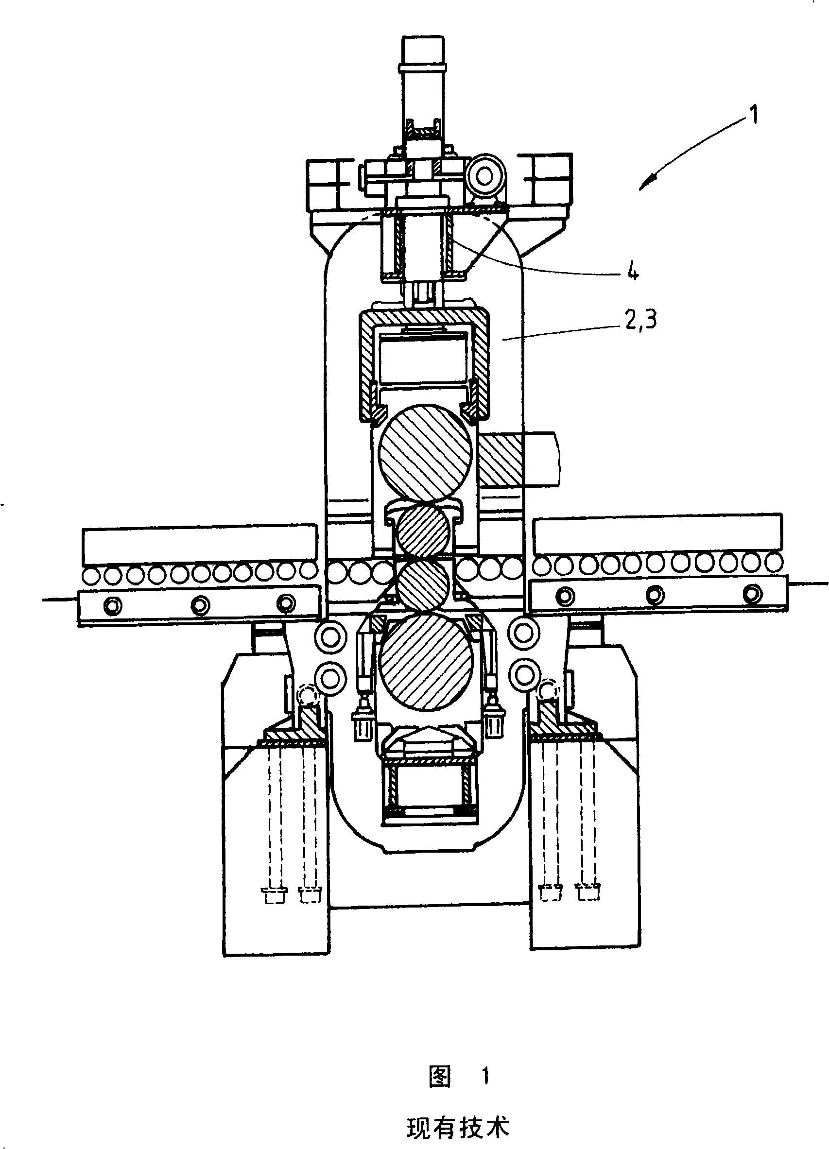
[0035] FIG. 1 shows a partially cut-away side view of a prior art rolling mill stand 1 with stands 2 , 3 and a stand cross member 4 connecting the stands 2 , 3 . Arranged in the frame crossbeam 4 is a backup roller balancing mechanism, the piston rod of which protrudes upwards from the frame crossbeam 4 .

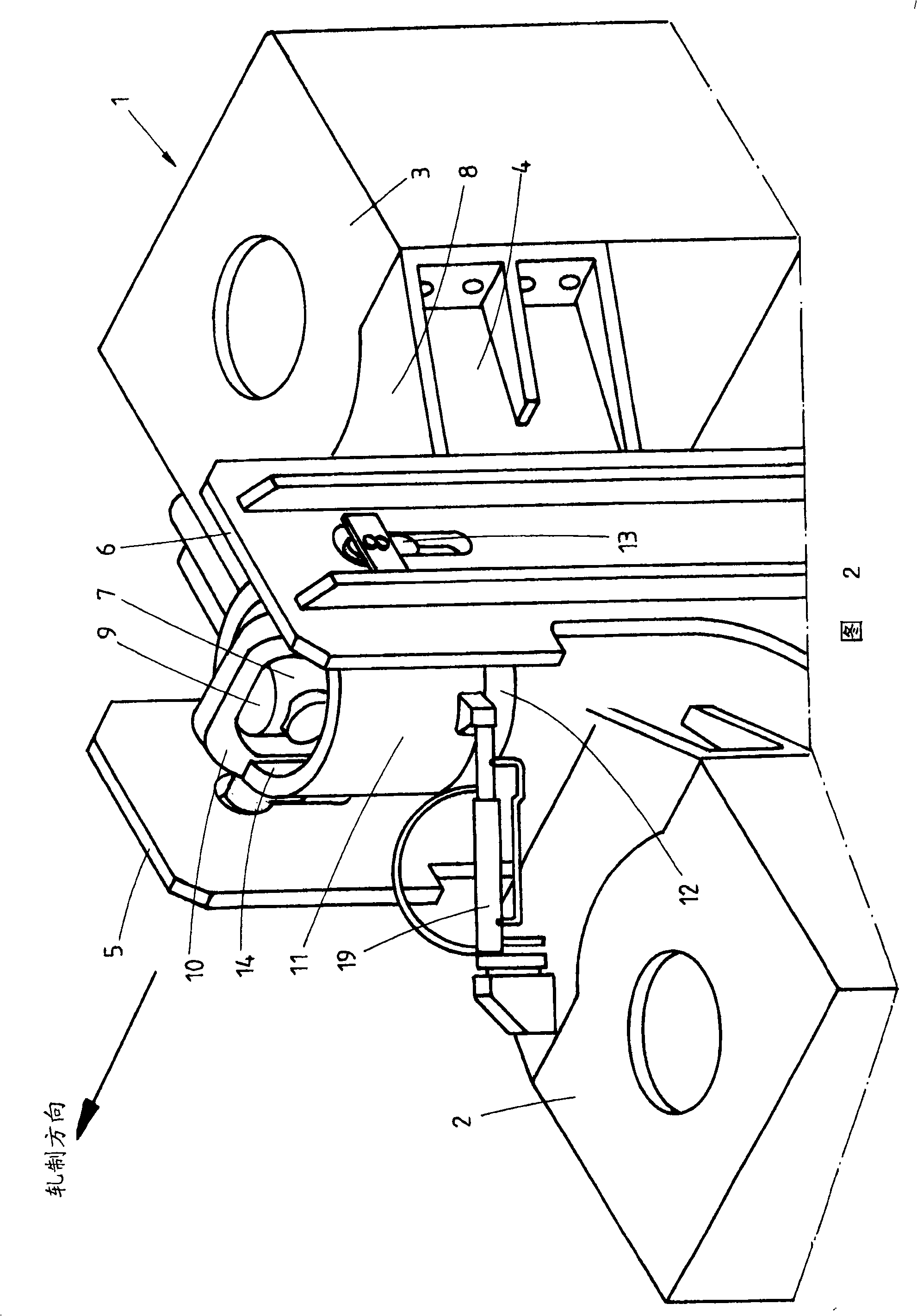
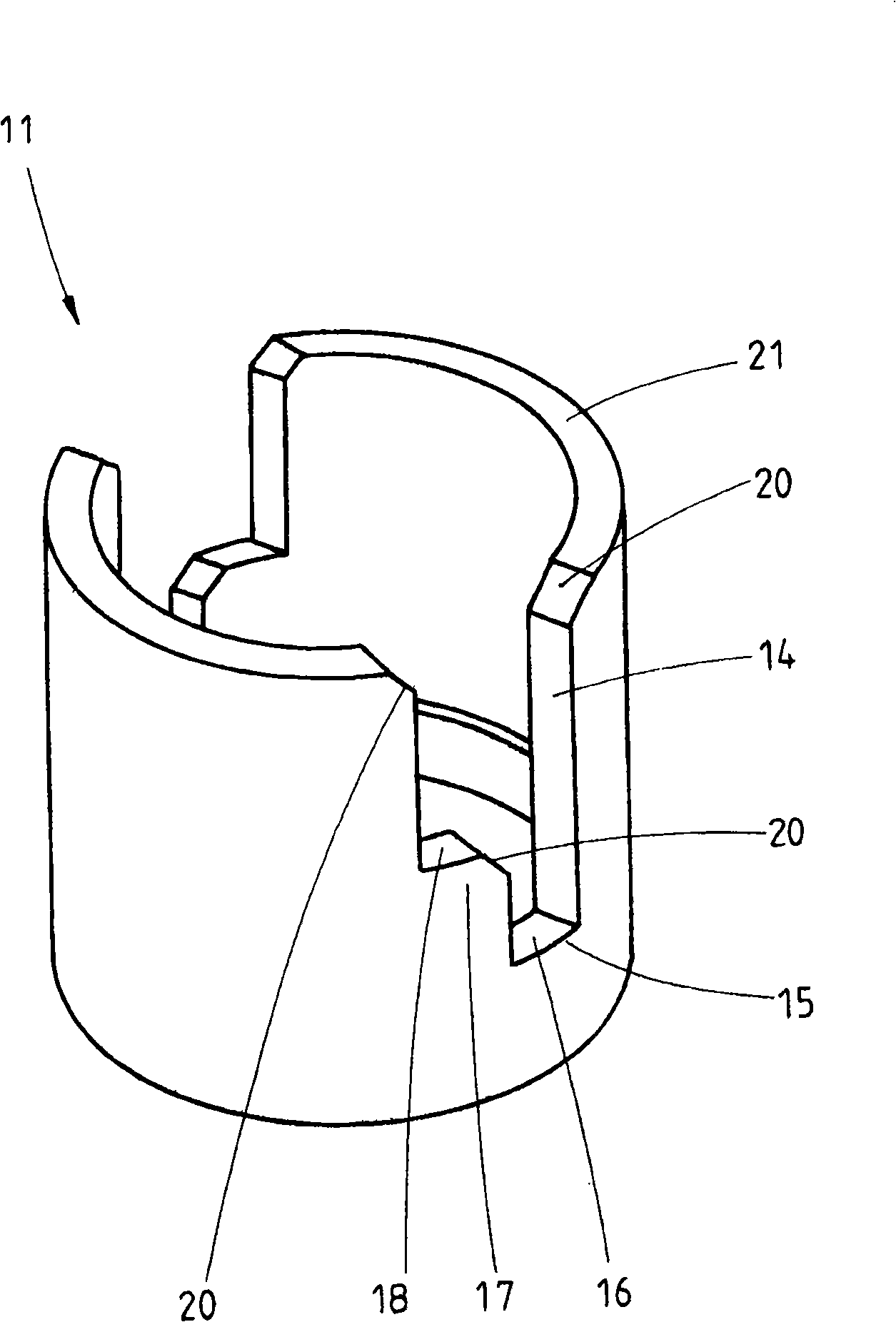
[0036] FIG. 2 shows a schematic three-dimensional view of a rolling stand 1 according to the invention, which has a left stand 2 and a right stand 3 . The two frames are connected to each other at their upper ends by a frame cross member 4 . The piston rod 7 protruding upwards from the frame cross member 4 is slotted at its outer end 9 and receives a yoke 10 . This yoke 10 , which is fastened, for example by pins, to the piston rod 9 is oriented in the rolling direction and engages with its ends in the holding arms 5 , 6 of the compensating mechanism. A rotating sleeve is arranged around said piston rod 7, which is supported on a balancing cylinder 22 of said balancing me...


PUM


Abstract

With a roll stand (1), in particular a thick plate roll stand with a right stand frame (2), a left stand frame (3), an upper stand cross beam (4) connecting said frames, at least one pair of working rollers, and one pair of support rollers and the appertaining inserts, as well as a balancing device with holding arms (5, 6), and a piston rod (7) that protrudes through the cross beam in the upward direction and that projects above the top surface (8) of the cross beam (4). A brace (10), located on the outer end (9) of the piston rod (7), is aligned in the direction of the roller and engages with the holding arms (5, 6) of the balancing device. A rotational sleeve (11) arranged between the top edge (12) of the balance cylinder (22) and the bottom edge (13) of the brace (10) clasps around the piston rod (7) and is thus supported on the cross beam (4), and has at least one continuous groove (14) into which the brace (10) can dip.

Description

technical field [0001] The invention relates to a rolling mill stand, in particular a plate rolling mill stand, with a right-hand stand, a left-hand stand, an upper stand connecting the two stands frame beam, at least one pair of work rolls and one pair of backup rolls and the associated bearing housings as well as a balancing mechanism with holding arms and an upper surface protruding upwards through the frame beam and protruding beyond the frame beam the piston rod. Background technique [0002] A known rolling mill stand is shown, for example, in FIG. 1 . The piston rod moves upwards or downwards in the backing roller balancing mechanism and thus forms a display device which shows the position of the backing roller balancing mechanism. [0003] A rolling stand is known from DE 101 16 988 A1, which has a mechanism for raising or lowering the intermediate roll track or the work roll track when changing rolls. Here, by means of the support roll-balance cylinder, the suppo...

Claims


Application Information

Patent Timeline
Patent Type & Authority Applications(China)
IPC IPC(8): B21B31/20
CPCB21B31/203B21B31/106B21B31/32
Inventor M·索佩B·齐瑟
Owner SMS DEMAG AG
Learn More