Concrete stirrer for double-horizontal shaft experiment

A technology for concrete mixers and tests, applied to mixers, mixers with rotating mixing devices, cement mixing devices, etc., can solve the problems that the structure needs to be further improved, achieve simple structure, sufficient mixing, and improve the convenience of operation Effect

Inactive Publication Date: 2010-06-02
SHANGYU HONGXING MACHINERY INSTR MFG
View PDF5 Cites 0 Cited by
  • Summary
  • Abstract
  • Description
  • Claims
  • Application Information

AI Technical Summary

Problems solved by technology

However, its structure needs to be further improved, and the ease of operation also needs to be improved.

Method used


Image

  • Concrete stirrer for double-horizontal shaft experiment
  • Concrete stirrer for double-horizontal shaft experiment
  • Concrete stirrer for double-horizontal shaft experiment

Examples


Embodiment Construction

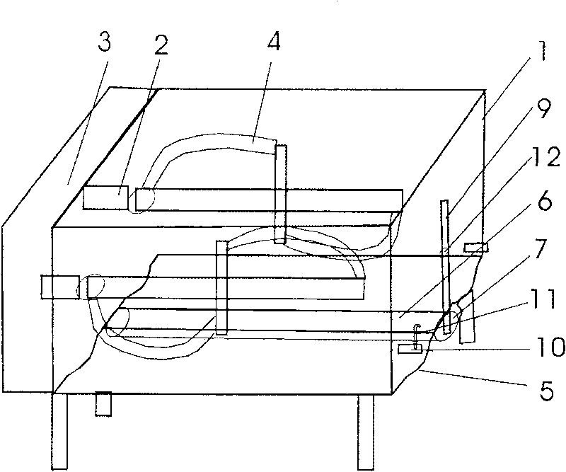
[0013] Such as figure 1 As shown, the concrete mixer for twin-horizontal shaft test of the present invention includes a barrel 1, and two parallel stirring shafts 2 horizontally arranged in the barrel, and the two stirring shafts 2 are in phase with the rotary mechanism 3 of the motor reduction box. Connect, have stirring curved blade 4 on the two stirring shafts 2, and above-mentioned structure is identical with the structure of the twin-shaft concrete mixer of prior art. In addition, components such as a control box can also be configured for actual needs. Since the above results have little connection with the inventiveness of the present invention, they are only briefly described.

[0014] The characteristics of the concrete mixer for twin-horizontal shaft test of the present invention are: the bottom of the barrel 1 has two depressions 5, the two depressions 5 are below the two stirring shafts 2, and the two depressions 5 are circular Arc, the radius of its arc is matche...


PUM

PropertyMeasurementUnit
angleaaaaaaaaaa

Abstract

The invention discloses a twin-horizontal-shaft concrete mixer for testing which comprises a cylinder, and two parallel stirring shafts which are horizontally arranged in the cylinder; the two parallel stirring shafts are connected with the slewing gear of a motor gearbox and provided with stirring vanes. The bottom of the cylinder is provided with two sink marks arranged at the lower part which the two stirring shafts are corresponding to; a discharge hole is arranged between the two stirring shafts; the lower part of the discharge hole is provided with a compass rotor; the discharge hole forms a tight fit with the rotor provided with a discharge passage. One end of the rotor is fixed with a push rod. Two push rod limit posts are arranged at the outside of the side wall of the cylinder. With the structure adopted, the two-horizontal shaft concrete mixer for testing of the invention has the advantages of simple structure, convenient operation, etc.

Description

technical field [0001] The invention relates to a concrete mixer, more specifically a concrete mixer for twin-shaft tests. Background technique [0002] The existing twin-shaft concrete mixer includes a barrel and two parallel stirring shafts horizontally arranged in the barrel, the two stirring shafts are connected with the rotary mechanism of the motor reducer, and there are stirring blades on the two stirring shafts. [0003] For example, the patent document (publication number: CN2601806) published on February 4, 2004 by the State Intellectual Property Office of the "Tipping Device for Concrete Mixer". The limit protruding shaft on the inner wall, the pendulum plate installed between the two rail rods rotatably around the limit protruding shaft, the connecting rod connecting the two pendulum plates, the elastic reset device and the manual pull cord, wherein the front end of the pendulum plate is set as The obliquely upward inclined body protrudes out of the front side o...

Claims


Application Information

Patent Timeline
Patent Type & Authority Patents(China)
IPC IPC(8): B01F7/08B28C5/14
Inventor 张关来田冠飞丁建彤张娟
Owner SHANGYU HONGXING MACHINERY INSTR MFG
Why Eureka
Try Eureka