
Aluminum melt furnace refining device

A technology for in-furnace refining and aluminum melt, applied in the field of in-furnace refiners, can solve the problems of low degassing and slag removal efficiency, short floating distance and time, etc. The effect of recontamination

Active Publication Date: 2009-01-21
SOUTHWEST ALUMINUM GRP
View PDF0 Cites 2 Cited by
  • Summary
  • Abstract
  • Description
  • Claims
  • Application Information

AI Technical Summary

Problems solved by technology

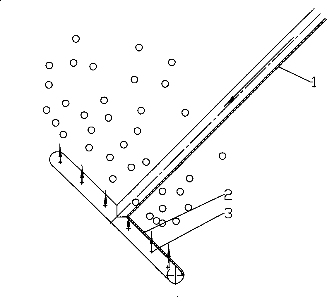
[0002] The structure of the furnace refiner used in the current aluminum melting furnace is as follows: figure 1 As shown, the outlet hole 3 on the head 2 of the refiner is in a vertical direction. After the refining gas enters the head 2 of the refiner from the inlet pipe 1, it is sprayed out from the outlet hole 3 and then directly floats upward and overflows the melt On the surface, since the bubbles have a certain initial velocity at the beginning, the floating distance and time of the bubbles in the melt are short, and the degassing and slag removal efficiency is low. At the same time, when the faster and more concentrated bubbles float out of the melt surface, the surface is more violent. The gushing phenomenon makes the melt react with water and oxygen above the melt, making the melt absorb hydrogen and produce oxidized slag inclusions

Method used


Image

  • Aluminum melt furnace refining device
  • Aluminum melt furnace refining device
  • Aluminum melt furnace refining device

Examples


Embodiment Construction

[0010] The present invention will be further described below in conjunction with the accompanying drawings and specific embodiments, so as to help understand the content of the present invention.

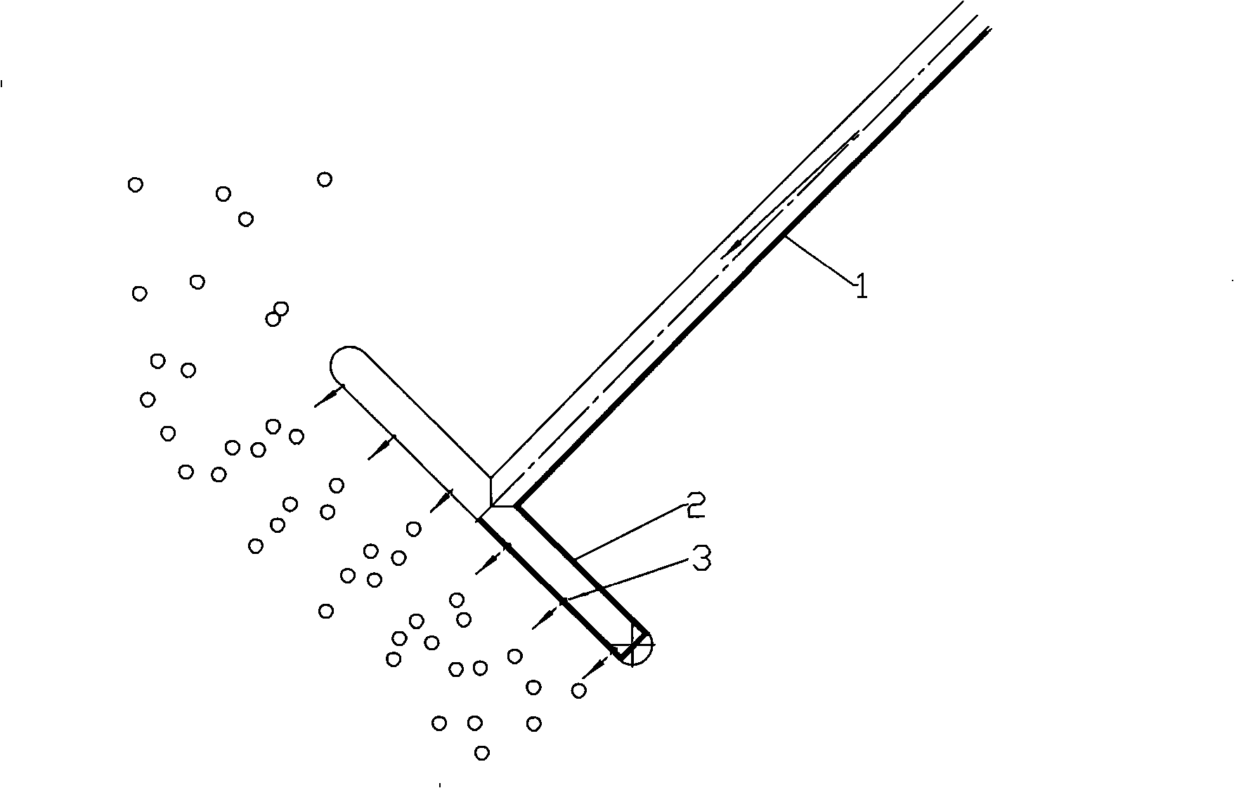
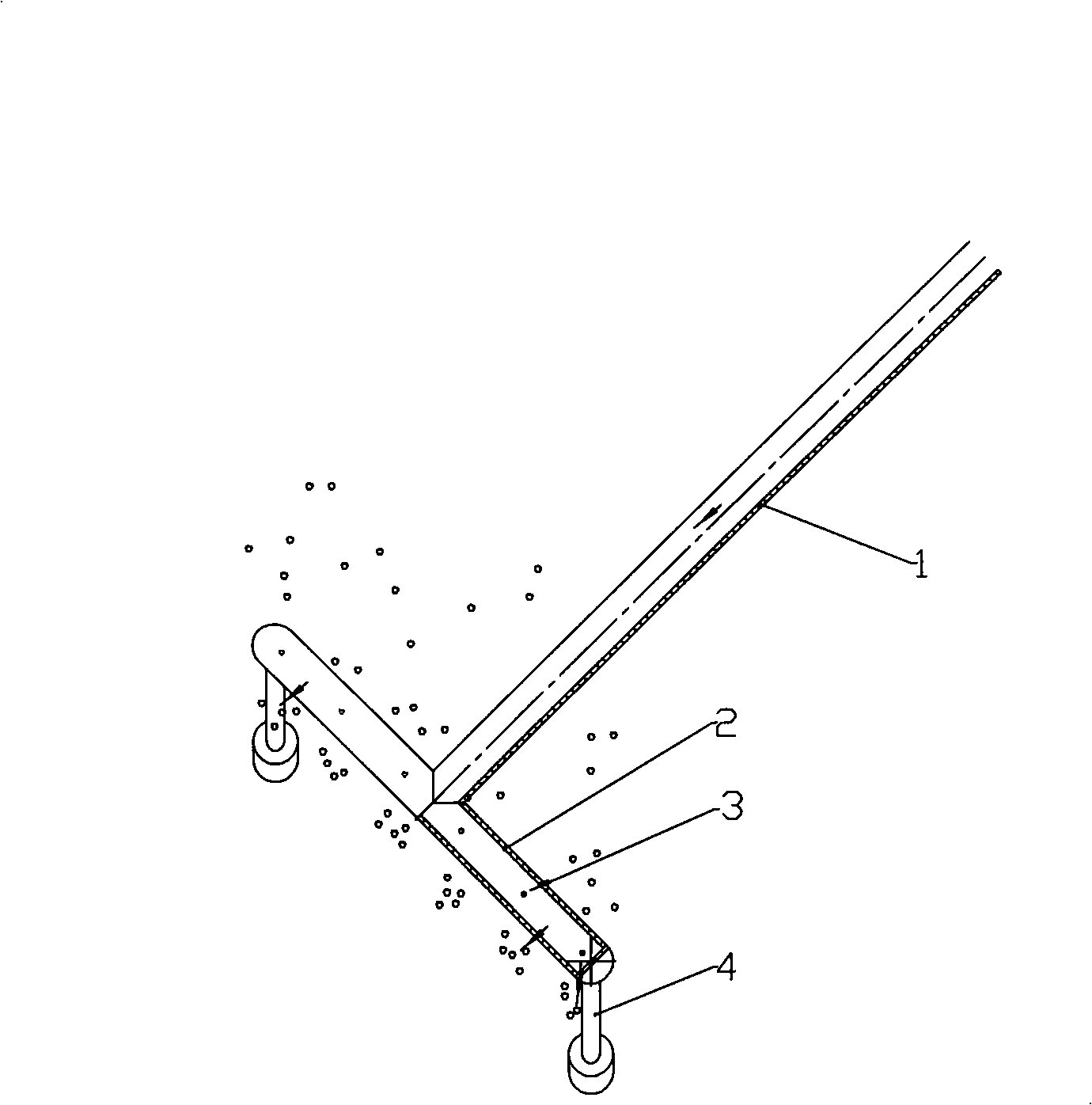
[0011] like figure 2 The shown refiner in the aluminum melting furnace includes a horizontally placed refiner head 2 connected to the inlet pipe 1 of the refiner. The refiner head 2 is a round tube, and the outlet on the refiner head is The air hole 3 is located on the tube wall at the level of the axis line of the refiner head. In this way, after the refined gas enters the refiner head 2 from the inlet pipe 1 and diverts to both ends, it is ejected horizontally from the air outlet 3 of the refiner head 2, and the formed bubbles will float forward for a certain distance along the direction of the air outlet, and at the same time Under the action of buoyancy, the upward overflow prolongs the residence time of the bubbles in the melt and the floating route, so that more hydrogen can...


PUM


Abstract

The invention discloses a refiner in an aluminum fused mass furnace, comprising a refiner head which is connected to an air inlet pipe of the refiner and horizontally placed. The refiner is characterized in that an air outlet on the refiner head is positioned on a horizontal plane where an axial line of the refiner head is positioned or on a pipe wall under the horizontal plane. The refiner improves degassing and deslagging effects and simultaneously can obviously reduce the spewing phenomenon of a fussed mass when air bubbles are overflowed from the surface of the fussed mass, and reduces secondary pollution of the fussed mass.

Description

technical field [0001] The invention relates to a furnace refiner for smelting aluminum. Background technique [0002] The structure of the furnace refiner used in the current aluminum melting furnace is as follows: figure 1 As shown, the outlet hole 3 on the head 2 of the refiner is in a vertical direction. After the refining gas enters the head 2 of the refiner from the inlet pipe 1, it is sprayed out from the outlet hole 3 and then directly floats upward and overflows the melt On the surface, since the bubbles have a certain initial velocity at the beginning, the floating distance and time of the bubbles in the melt are short, and the degassing and slag removal efficiency is low. At the same time, when the faster and more concentrated bubbles float out of the melt surface, the surface is more violent. The gushing phenomenon causes the melt to react with water and oxygen above the melt, causing the melt to absorb hydrogen and produce oxidized slag inclusions. Contents o...

Claims


Application Information

Patent Timeline
IPC IPC(8): C22B21/06
Inventor 牟大强唐剑韦志宏
Owner SOUTHWEST ALUMINUM GRP
Learn More