

Saline soil area combined drain system and combined water drain forced ramming foundation treating method thereof
A drainage system and foundation treatment technology, applied in soil protection, infrastructure engineering, construction, etc., can solve the problems of poor saline soil treatment effect, long construction period, and insignificant foundation bearing capacity, and shorten the construction period of foundation treatment. , The effect of improving the bearing capacity and modulus of the foundation and saving the cost of foundation treatment
- Summary
- Abstract
- Description
- Claims
- Application Information
AI Technical Summary
Problems solved by technology
Method used
Image

Examples
Embodiment 1
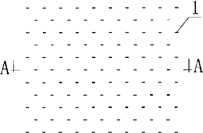
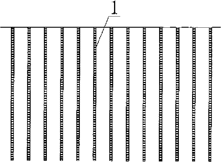
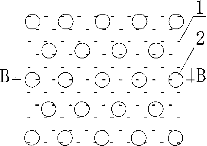
[0062] Embodiment 1 Referring to Figure 9, this combined drainage system for saline soil areas is characterized in that it is composed of plastic drainage strips 1 arranged longitudinally in the foundation soil and sand and gravel drainage piles 2 distributed therebetween to form a drainage system one by one. channel, the upper end of the drainage channel in a local area merges into a ramming pit 5, and a drainage pump 9 is arranged in the ramming pit, and the drainage pump 9 is connected with a drainage pipe 10.
[0063] This method of combined drainage and dynamic compaction foundation treatment in saline soil areas requires the following design to be completed before construction to determine the basic design parameters:
[0064] 1. Select the model of the plastic drainage belt, and determine the length, arrangement, spacing, etc. of the plastic drainage belt.
[0065] 2. Determine the pile diameter, pile length, pile distance and pile body material of the drainage pile.
...
Embodiment 2
[0076] Embodiment 2 Referring to Figure 1116, the difference from Embodiment 1 is that the construction sequence of the combined drainage system in Step 1 is to construct the sand and gravel drainage pile 2 first and then construct the plastic drainage belt 1 .
[0077] Refer to Figure 17-23 for the construction steps of the above-mentioned gravel drainage piles:
[0078] Referring to Figure 17 for step a, the pile driver is in place and the pile pipe 7 is ready. The pile tube is a variable-diameter pile tube, which is selected according to the designed feeding amount of each sand and gravel drainage pile. The pile hole formed by the variable-diameter pile pipe is larger than the designed pile diameter.
[0079] Referring to Figure 18 for step b, start the pile driver to make the pile pipe 7 sink vertically at the set position.
[0080] Refer to Figure 19 for step c, the pile pipe is sunk to the design depth.
[0081] Referring to Fig. 20 for step d, put the coarse granular...
PUM
| Property | Measurement | Unit |
|---|---|---|
| Width | aaaaa | aaaaa |
| Thickness | aaaaa | aaaaa |
Abstract
Description
Claims
Application Information