Integrated microstructure backlight system

A technology of backlight system and micro optics, applied in the field of backlight system, can solve problems such as the inability to meet the integration requirements of backlight modules

Active Publication Date: 2009-01-21
SHENZHEN UNIV +1
View PDF1 Cites 11 Cited by
  • Summary
  • Abstract
  • Description
  • Claims
  • Application Information

AI Technical Summary

Problems solved by technology

[0006] In order to solve the technical problem that in the backlight system of the prior art, at least one independent prism sheet needs to be used to condense the outgoing light of the light guide plate, which cannot meet the integration requirements of the backlight modul

Method used


Image

  • Integrated microstructure backlight system
  • Integrated microstructure backlight system
  • Integrated microstructure backlight system

Examples


Embodiment Construction

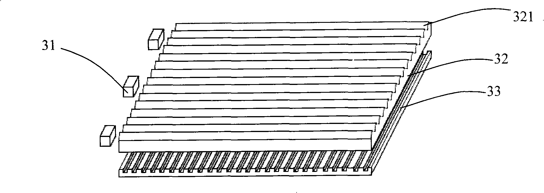
[0028] Such as image 3 as shown, image 3 It is a structural schematic diagram of an embodiment of the integrated microstructure backlight system of the present invention. The backlight system of this embodiment includes: a light source 31 , a light guide plate 32 and a reflection sheet 33 . Wherein, the light guide plate 32 includes a light incident surface for receiving light emitted by the light source 31, a light exit surface for emitting light, and a bottom surface opposite to the light exit surface, and a micro-optical light concentrating structure is arranged on the light exit surface of the light guide plate 32. The micro-optical light-concentrating structure can be a prism, a cone, a pyramid, a truncated cone, a truncated prism, a pyramid with a concave top area, a cone with a concave top area, a prism with a concave top area, or a truncated cone with a concave top area, such as image 3 The microprism structure 321 shown, Figure 7 is a pyramidal structure with a...


PUM

PropertyMeasurementUnit
Bottom widthaaaaaaaaaa

Abstract

The invention relates to a backlight system of an integral microstructure, which comprises a light guide plate, a light source and a reflector plate, wherein the light guide plate is provided with a light inlet surface, a light outlet surface and a bottom surface opposite to the light outlet surface, the light source is arranged near the light outlet surface, the reflector plate is arranged near the bottom surface, the light outlet surface of the light guide plate is equipped with a micro-optics light focusing structure, and the reflector plate is equipped with a micro-reflection structure. By means of the above structure, the reflecting surface of the micro-reflection structure of the reflector plate reflects light, a light reflecting field can be focused and modulated via changing the inclination angle of the reflecting surface, and the brightness value in an ideal vision field of the light guide plate can be further increased by engaging with the micro-optics light focusing structure of the light guide plate, thereby avoiding using traditional prism sheets, reducing the number of device elements, realizing high integration of the backlight system, increasing the optical energy usage, and reducing the cost.

Description

【Technical field】 [0001] The invention relates to a backlight system, in particular to an integrated microstructure backlight system for passive luminescence flat panel display. 【Background technique】 [0002] Existing passive light-emitting flat-panel display devices, such as liquid crystal displays (Light crystal displays, LCDs), have the advantages of light weight, thin thickness, low power consumption, and no radiation, so they are widely used in mobile phones, digital cameras, video cameras, mp3 and other fields. Since the liquid crystal material itself does not have light-emitting properties, it is necessary to provide an additional light source system for it to realize the display function. [0003] Such as figure 1 as shown, figure 1 It is a structural schematic diagram of an existing backlight system involved in US Patent No. 6,443,583 published by 3M Company of the United States on September 3, 2002. The backlight system includes a light source 11, a light guide...

Claims


Application Information

Patent Timeline
IPC IPC(8): F21V7/04F21V8/00G02F1/13357G02F1/1335
Inventor 徐平陈祥贤
Owner SHENZHEN UNIV
Why Eureka
Try Eureka