
Plane reverse F type tri-frequency antennae

A planar and antenna technology, applied in the field of tri-frequency planar inverted-F antennas, can solve the problems of mismatching wireless network frequency bands in the working frequency band and inconvenient communication for users, and achieve the effects of strong practicability, promotion value, and strong adaptability

Inactive Publication Date: 2009-01-21
MITAC PRECISION TECH(KUNSHAN) CORP
View PDF0 Cites 1 Cited by
  • Summary
  • Abstract
  • Description
  • Claims
  • Application Information

AI Technical Summary

Benefits of technology

The new design allows users to easily attach an electronic device (such as their phone) wirelessly on different devices without having to be physically connected or rewiring them yourself. This improves flexibility and usability while also being cost-effective compared to previous designs that had fixed connections between components like wires.

Problems solved by technology

This patented technical problem addressed by the patents relates to improving the design of conventional nonvolatile memory cards such as Wireless Local Area Networking Access Point (WiFi), Bluetooth® devices, etc., while also ensuring they can effectively communicate over multiple types of signals without requiring separate hardware components like USB ports or other interfaces.

Method used


Image

  • Plane reverse F type tri-frequency antennae
  • Plane reverse F type tri-frequency antennae

Examples


Embodiment Construction

[0012] In order to have a deeper understanding of the structure and technical features of the present invention, detailed description will be given below in conjunction with the accompanying drawings.

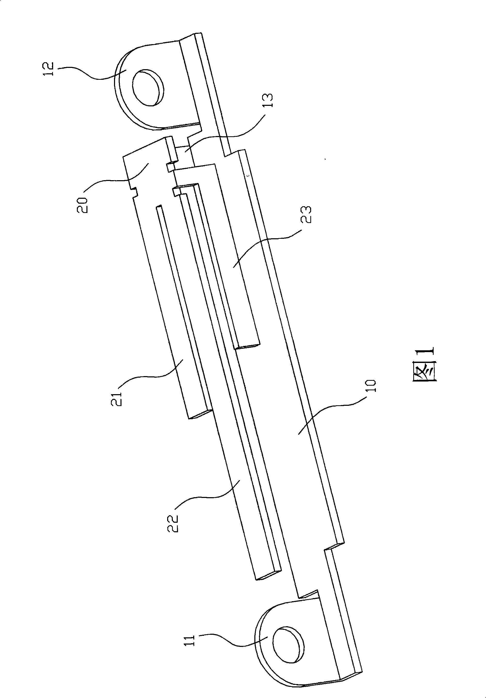
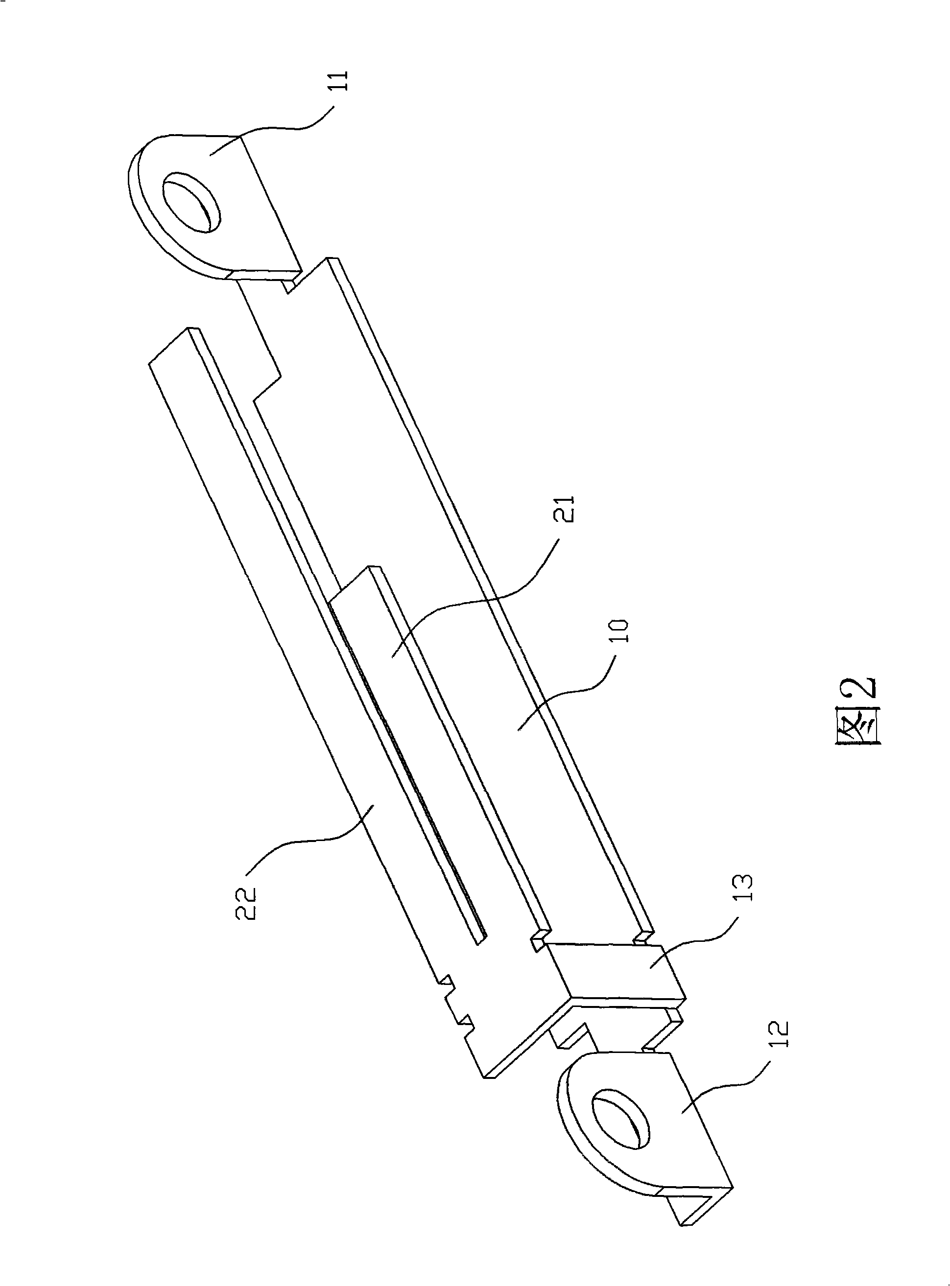
[0013] Please refer to FIG. 1 and FIG. 2 , which are schematic views of the front and back structures of a preferred embodiment of the present invention, respectively. The planar inverted F-type tri-band antenna provided by the present invention is used for receiving and transmitting notebook computer wireless network signals. The antenna includes a grounding part 10, which is a strip-shaped metal plate. The fixing part 11, in this embodiment, the fixing part 11 fixes the antenna inside the notebook computer by a screw (not shown); the antenna also includes an access part 12, and the access part 12 is arranged on the grounding part 10, the end opposite to the fixed portion 11, the access portion 12 is connected to a signal source, in this embodiment, the access portion 12 is co...


PUM


Abstract

The invention discloses a plane inverse-F triple-band antenna applicable to receiving and emitting wireless signals of notebook computers, comprising a grounding part which is a strip metal plate, a fixing part is arranged at one end of the grounding part, and the antenna is fixed inside the notebook computer by the fixing part; a switch-in part arranged on one end of the grounding part opposite to the fixing part, and the switch-in part is connected with the wireless adaptor arranged inside the notebook computer; an emitting and receiving part which is arranged above the position between the two ends of the grounding part, the emitting and receiving part is connected with one end of the grounding part, and the emitting and receiving part comprises a first emitting and receiving unit, a second emitting and receiving unit and a third emitting and receiving unit, the three emitting and receiving units are used to receive and send three wireless network signals in different wave-bands.

Description


Claims


Application Information

Patent Timeline
Owner MITAC PRECISION TECH(KUNSHAN) CORP
Learn More