Wind power system and method of operating it

A technology of wind power and control system, applied in the direction of control system, wind turbine, wind turbine combination, etc., can solve problems such as damage to generators

Active Publication Date: 2009-01-21
GAMESA INNOVATION & TECH SA
View PDF5 Cites 12 Cited by
  • Summary
  • Abstract
  • Description
  • Claims
  • Application Information

AI Technical Summary

Problems solved by technology

[0015] Now, the problem with the system disclosed in WO2007 / 006565 is that although it increases the power output, this can actually damage the mechanical parts of the generator, for example due to excessive torque

Method used


Image

  • Wind power system and method of operating it
  • Wind power system and method of operating it
  • Wind power system and method of operating it

Examples


Embodiment Construction

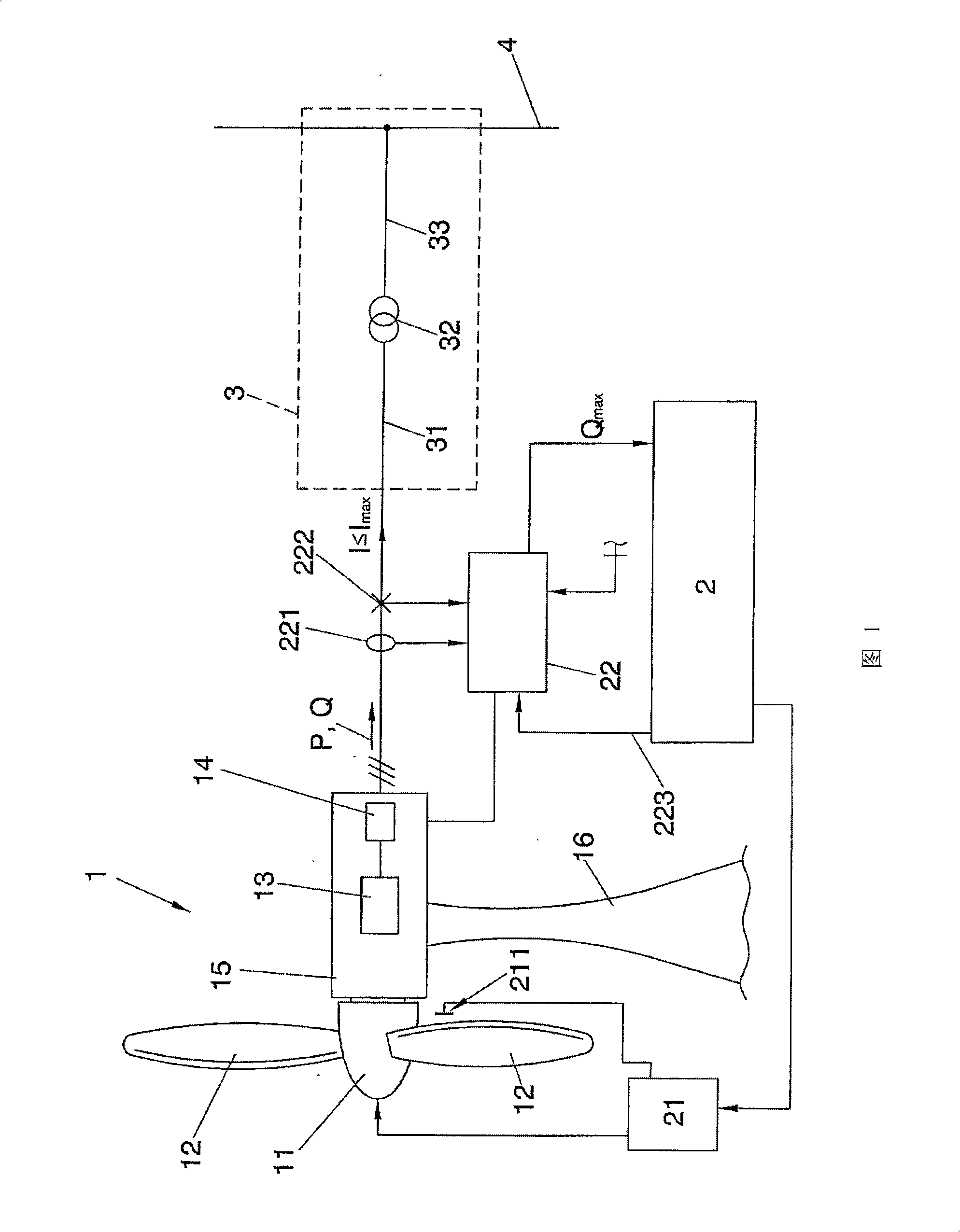
[0037] Figure 1 schematically shows the structure of a wind power generation system comprising a wind turbine 1 having a rotor 11 with blades 12 arranged such that it is rotated by the wind and thus produces a corresponding rotation, sometimes by a generator 13 (not shown) (ie, the gearbox of the rotor portion of the generator, which also includes a stator portion). The generator 13 produces an output AC voltage and can be connected to an electrical converter 14; at present, many different converter designs and structures are well known in the art, so it is not necessary to discuss them further here; the converters that can be used within the framework of the present invention Examples of converter configurations include full power converter configurations (such as the one disclosed in US-A-5083039) and doubly-fed induction generator configurations such as those using back-to-back power converters (as disclosed in US-A-2003 / 0151259 published converters); the contents of these ...


PUM


Abstract

The wind power system comprises an installation (1) for generating electrical power from wind by means of at least one power generating turbine arranged to be rotated by wind, and a control system (2) including a power controller (22). The power controller (22) is configured to keep the magnitude of the total current below a pre-set maximum magnitude (Imax).

Description

technical field [0001] The present invention relates to the field of wind power systems and devices, and in particular to the control of providing power generated by the system and devices to a network or grid for power distribution. Background technique [0002] A wind power system includes one or more wind generators or turbines arranged to generate electrical energy through wind-induced rotation. The electrical energy produced by one or more of these generators (for example several generators forming or constituting a so-called "wind farm") is supplied to a network or grid for distribution. Usually, a large number of electricity generators are connected to the same grid, and usually several electricity consumers are also connected to the grid. [0003] In order for the voltage and frequency on the grid to remain substantially constant, it is important that the power input to the grid at each moment is substantially equal to the power consumed. Therefore, electricity gen...

Claims


Application Information

Patent Timeline
Patent Type & Authority Applications(China)
IPC IPC(8): H02J3/38H02J3/46H02P9/00
CPCY02E10/763F05B2270/337Y02E10/723H02J3/386H02J3/382F03D7/0284F03D9/003F03D7/0272F03D9/255H02J2300/28H02J3/381Y02E10/72Y02E10/76H02J3/50
Inventor B·安德森
Owner GAMESA INNOVATION & TECH SA
Why Eureka
Try Eureka