Motor bearing structure

A technology of bearings and motors, which is applied in the field of motor bearing structures of cooling fans, can solve problems such as damage and increased noise, and achieve good buffering effects

Inactive Publication Date: 2009-01-21
FU ZHUN PRECISION IND SHENZHEN +1
View PDF0 Cites 4 Cited by
  • Summary
  • Abstract
  • Description
  • Claims
  • Application Information

AI Technical Summary

Problems solved by technology

[0003] When the cooling fan is working, the coil of the stator structure 11 generates a changing magnetic field after being energized, and interacts with the magnet on the rotor structure 15 to push the rotor structure 15 to run. The ground will

Method used


Image

  • Motor bearing structure
  • Motor bearing structure
  • Motor bearing structure

Examples


Embodiment Construction

[0013] The present invention will be further described below in conjunction with the embodiments with reference to the accompanying drawings.

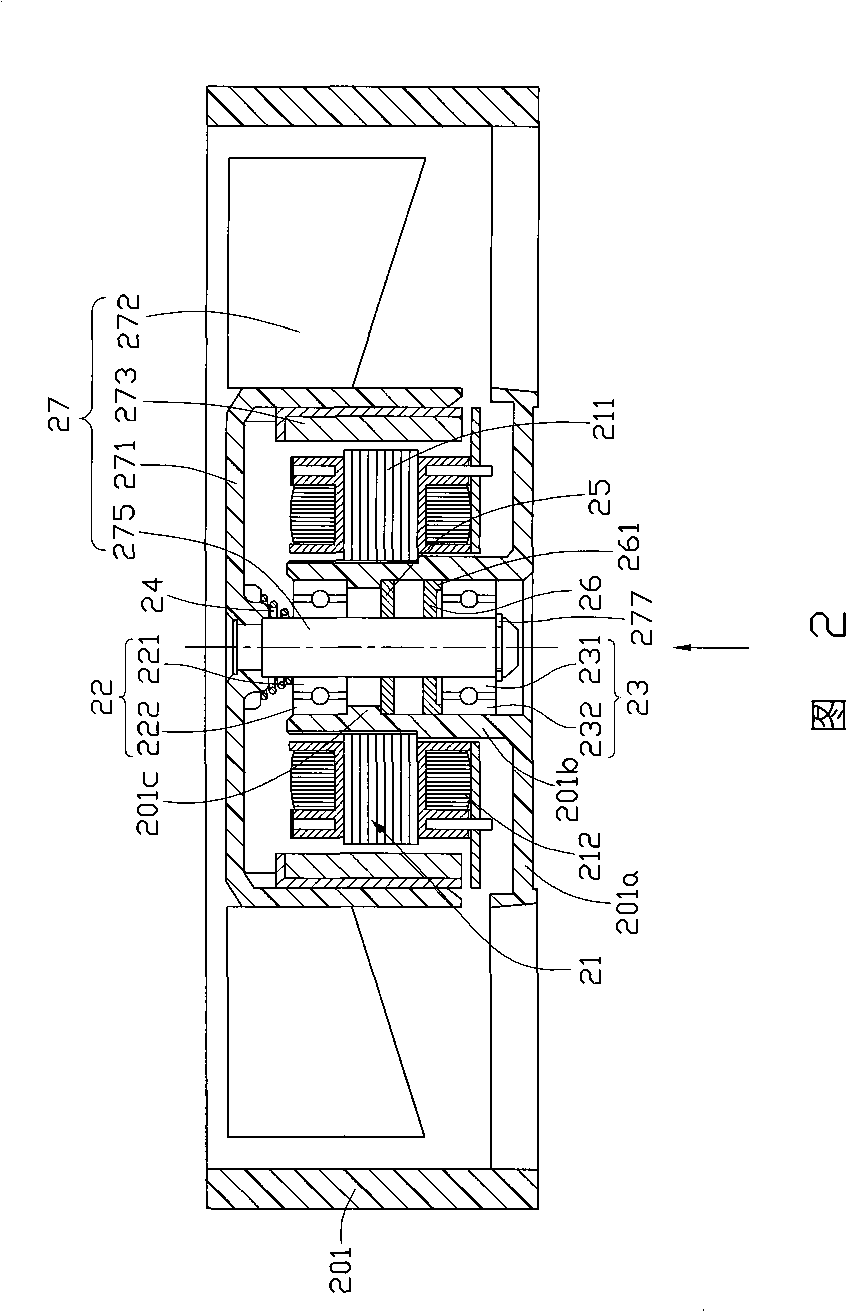
[0014] Figure 2 is a schematic cross-sectional view of the first embodiment of the motor bearing structure of the present invention, the motor bearing structure is arranged in an outer frame 201 of a heat dissipation fan, the bottom center of the outer frame 201 is provided with a stator seat 201a, the stator A hollow shaft tube 201b is arranged upward in the middle of the seat 201a, and a support portion 201c is protruded inwardly from the middle of the inner surface of the hollow shaft tube 201b. The motor bearing structure includes a stator 21, a first ball bearing 22, a second ball bearing Bearing 23 and a rotor 27.

[0015] The stator 21 is fixed on the periphery of the hollow shaft tube 201b, and includes a silicon steel sheet group 211 and a coil group 212 wound on the silicon steel sheet group 211 .

[0016] Both the first bal...


PUM


Abstract

The present invention provides a motor bearing structure and comprises a rotor and a ball bearing. The rotor is provided with a rotating shaft; the ball bearing is arranged in a hollow shaft tube; a buffering structure is arranged in the hollow shaft tube, and comprises a first magnet and a second magnet; the first magnet and the second magnet are arranged opposite to each other, and the opposite surfaces have the same polarity; one of the magnets is adjacently connected with the ball bearing; the rotating shaft passes through the first magnet, the second magnet and the ball bearing. Because the opposite surfaces of the first magnet and the second magnet have the same polarity, the two magnets can generate acting force to repel each other, thus the motor bearing structure has the buffering function in the force-bearing direction, which protects the ball bearing and simultaneously resets the ball bearing into the original position.

Description

technical field [0001] The invention relates to a motor bearing structure, in particular to a motor bearing structure of a cooling fan. Background technique [0002] As shown in Figure 1, the existing motor bearing structure usually includes a stator structure 11, two ball bearings 12, 13, a spring 14 and a rotor structure 15, the stator structure 11 is fixed on a hollow shaft tube 111 of the cooling fan , the ball bearings 12, 13 are respectively arranged in the hollow shaft tube 111, and abut against the inner wall of the hollow shaft tube 111, the spring 14 is arranged between the rotor structure 15 and the ball bearing 12 at the upper end, the rotor structure 15 A rotating shaft 151 is provided, and the rotating shaft 151 passes through the spring 14 and the ball bearings 12 and 13 respectively. [0003] When the cooling fan is working, the coil of the stator structure 11 generates a changing magnetic field after being energized, and interacts with the magnet on the rot...

Claims


Application Information

Patent Timeline
IPC IPC(8): H02K7/08
Inventor 林雨利黄英敏杨之亚彭志坚
Owner FU ZHUN PRECISION IND SHENZHEN
Why Eureka
Try Eureka