Aluminium alloy compression casting pan with compound bottom and compound technique thereof

A composite process, aluminum alloy technology, applied in special materials for cooking utensils, cooking utensils, household appliances, etc., can solve the problems of small effective area, surface damage of induction cooker, and insufficient flatness of film

Active Publication Date: 2010-08-11
ZHEJIANG CHUNZHOU ALUMINUM IND
View PDF0 Cites 0 Cited by
  • Summary
  • Abstract
  • Description
  • Claims
  • Application Information

AI Technical Summary

Problems solved by technology

[0002] At present, most of the composite-bottom die-casting pots that can be used in induction cookers are mechanically riveted composite-bottom pots. This kind of composite-bottom pot uses riveting nails to fix the stainless iron composite bottom sheet on the bottom of the pot body. The effective area of ​​the eddy current on the compound film is small, so the thermal efficiency is low; and there are defects such as complex manufacturing of molds and parts, and poor connection strength between the pot body and the film; the stainless iron compound film is uneven and long-term Use will also cause damage to the surface of the induction cooker
In addition, there are some composite bottom die-casting pots that pre-process the connection structure on the stainless iron bottom sheet. During die-casting, the connection structure is integrated with the pot body through die-casting, although it can better solve the problems of low thermal efficiency and insufficient flatness of the bottom sheet. , but there are still disadvantages such as complex manufacturing of molds and parts, high processing difficulty, and poor connection strength; especially during die-casting, the positioning reliability of the composite film in the die-casting mold is poor, which will lead to a high rate of waste and defective products. High consumption, so the production cost is not easy to control

Method used


Image

  • Aluminium alloy compression casting pan with compound bottom and compound technique thereof
  • Aluminium alloy compression casting pan with compound bottom and compound technique thereof
  • Aluminium alloy compression casting pan with compound bottom and compound technique thereof

Examples


Embodiment Construction

[0018] The present invention will be further described below with reference to the accompanying drawings and examples.

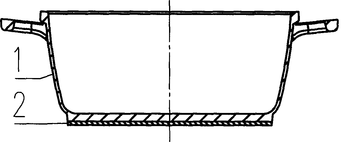
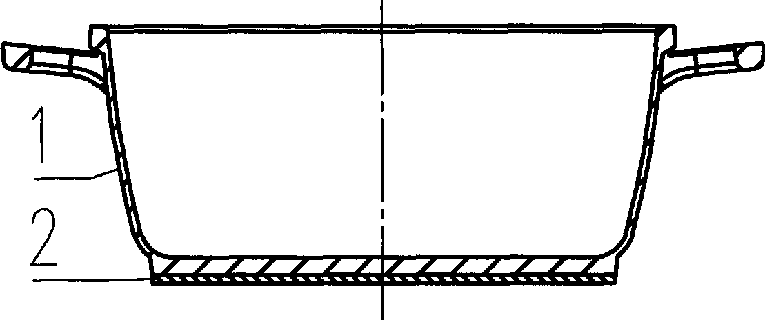
[0019] Referring to Fig. 1, the aluminum alloy die-casting pot with a composite bottom includes an aluminum alloy die-casting pot body 1 and a stainless iron compound base 2, and the stainless iron compound base 2 is directly laminated and composited with the pot body 1 as a whole. 2 on. Referring to Fig. 2, the aluminum alloy die-casting pot with composite bottom can be manufactured by the following process: first, the aluminum alloy die-casting pot body 1 is die-casted on a die-casting machine; then the surface of the pot body is cleaned; Apply the compounding agent; then put the bottom of the aluminum alloy die-casting pot body upside down, and then stick the side of the stainless iron film coated with the compounding agent on the bottom of the pot body; The rusty iron complex film is pressed tightly on the bottom of the pot, and the pressing pressure va...


PUM


Abstract

The invention relates to an aluminum alloy die-casting pan with a composite bottom, which comprises an aluminum alloy die-casting pan body and a stainless iron composite bottom plate, and is characterized in that the stainless iron composite bottom plate is directly overlaid with the bottom part of the pan body to integrate as a whole. The invention also relates to a complex process of the aluminum alloy die-casting pan with the composite bottom, wherein, the steps of die casting, surface cleaning, complexing agent coating, plate pasting, compounding, pressure retaining, cooling, surface follow-up processing, and the like, are adopted to form the aluminum alloy die-casting pan with the composite bottom. The aluminum alloy die-casting pan with the composite bottom in the invention has the advantages of simple structure, reliable compounding, high thermal efficiency, stable resistance performance of thermal fatigue, etc. The complex process of the invention is simple for application andis applicable to the use on an induction cooker.

Description

technical field [0001] The invention belongs to the field of cooking utensils and relates to an aluminum alloy die-casting pot with a composite bottom and a composite process thereof. Background technique [0002] At present, most of the composite-bottom die-casting pots that can be used in induction cookers are mechanically riveted composite-bottom pots. This kind of composite-bottom pot uses riveting nails to fix the stainless iron composite bottom sheet on the bottom of the pot body. The effective area of ​​the eddy current on the compound film is small, so the thermal efficiency is low; and there are defects such as complex manufacturing of molds and parts, and poor connection strength between the pot body and the film; the stainless iron compound film is uneven and long-term Using it will also cause damage to the surface of the induction cooker. In addition, there are some composite bottom die-casting pots that pre-process the connection structure on the stainless iron...

Claims


Application Information

Patent Timeline
Patent Type & Authority Patents(China)
IPC IPC(8): B22D17/00A47J36/02A47J27/00B23P15/00
Inventor 朱金洪
Owner ZHEJIANG CHUNZHOU ALUMINUM IND
Why Eureka
Try Eureka