Electric pressure cooker

A technology of electric pressure cooker and pot cover, which is applied in the direction of pressure cooker and contact parts, etc., to achieve the effect of safe operation of deflation, improvement of food taste, and easy manufacture and installation

Inactive Publication Date: 2009-01-28
JOYOUNG CO LTD
View PDF2 Cites 4 Cited by
  • Summary
  • Abstract
  • Description
  • Claims
  • Application Information

AI Technical Summary

Problems solved by technology

But for the screw-in electric pressure cooker, in order to realize the installation of electrical components in the lid, the electrical connection between the lid and the pot body must be solved first.

Method used


Image

  • Electric pressure cooker
  • Electric pressure cooker
  • Electric pressure cooker

Examples


Embodiment 1

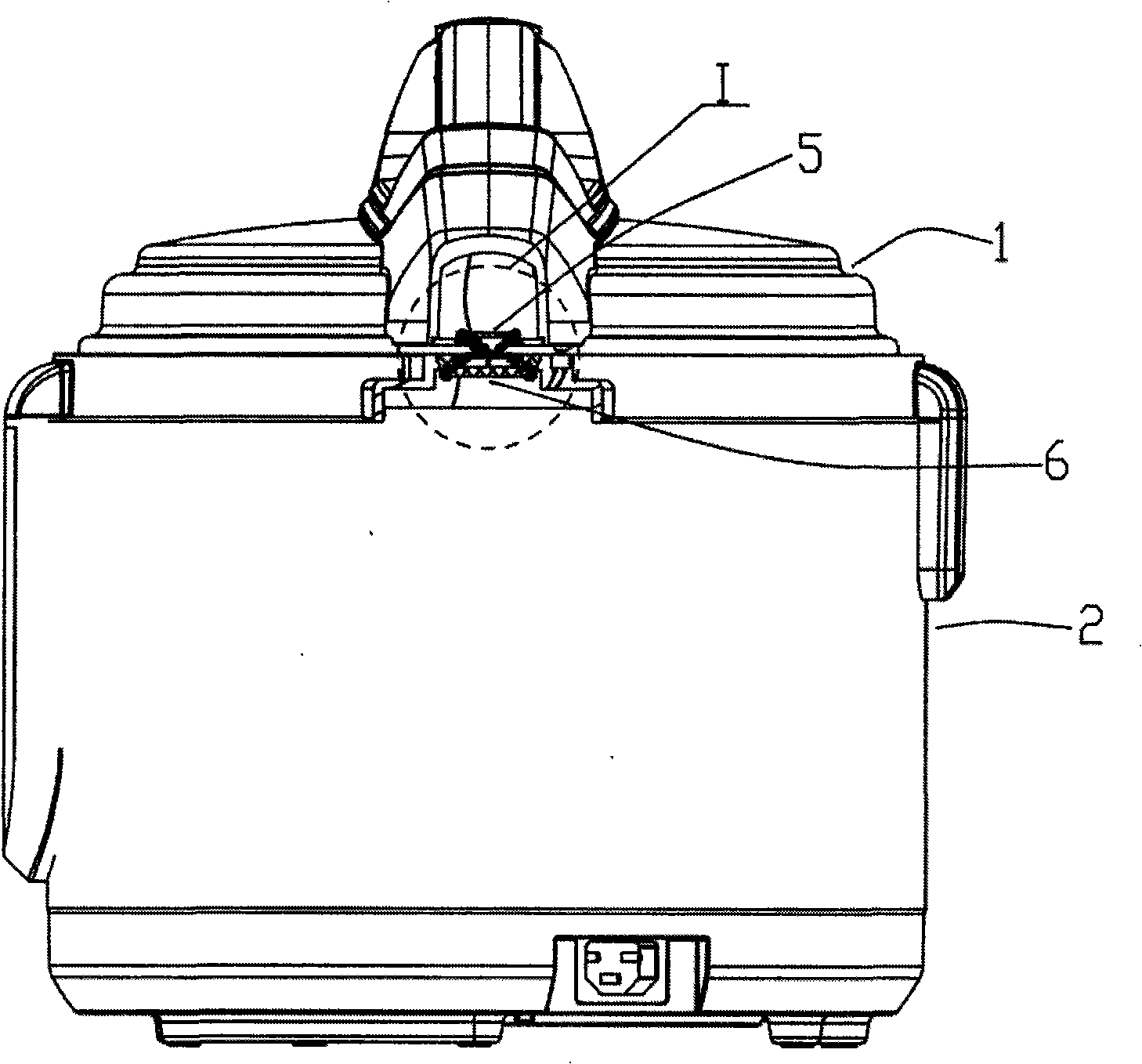
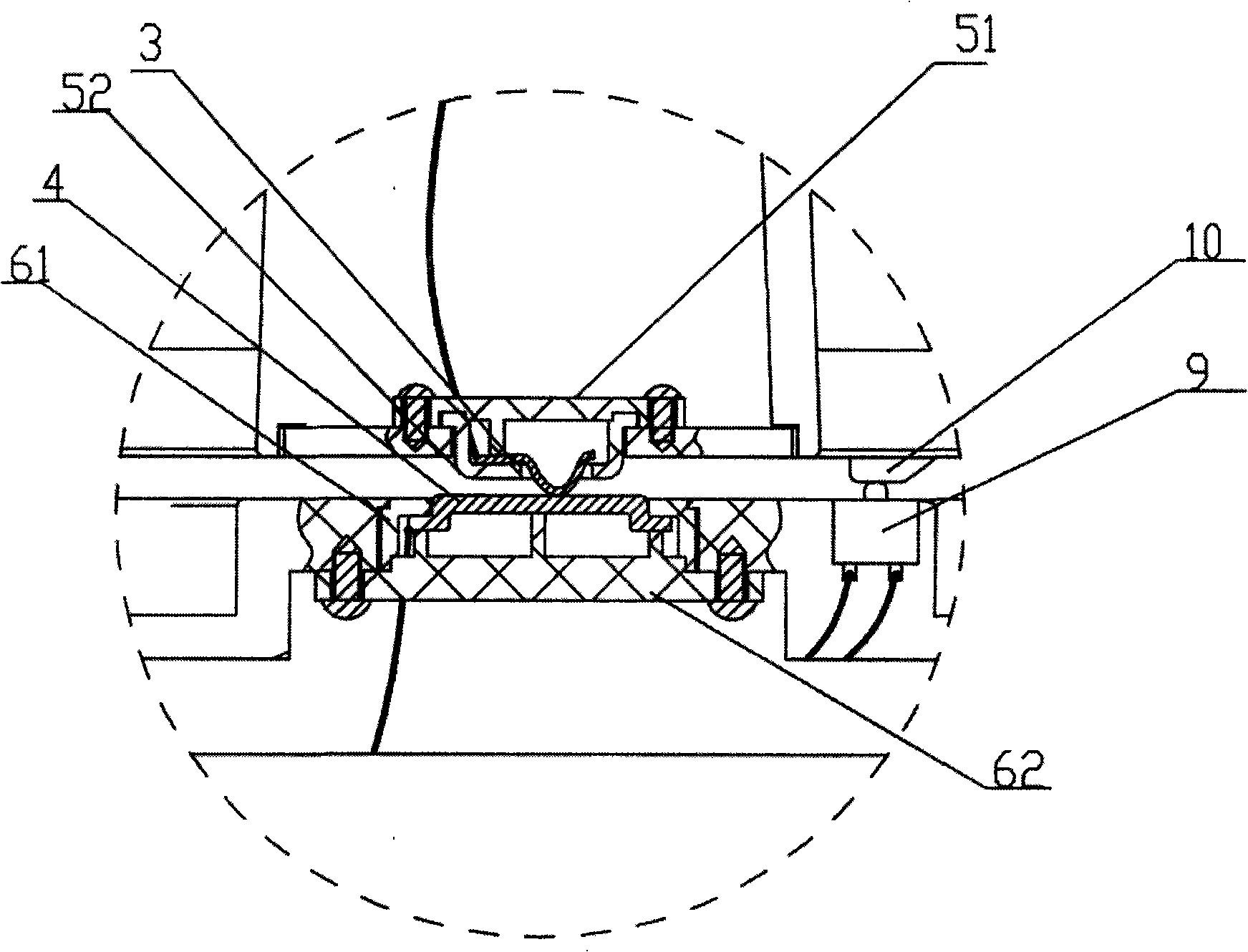
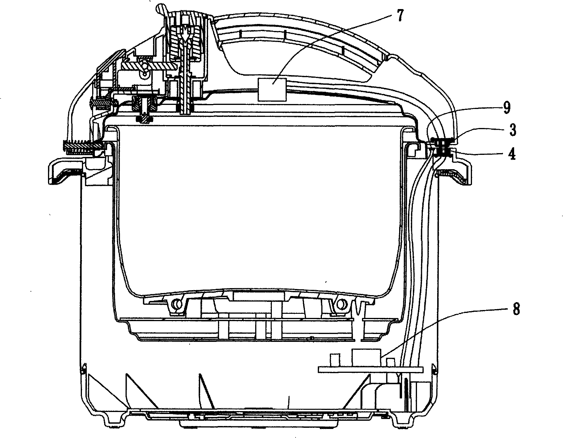
[0028] Such as figure 1 , figure 2 , image 3 , Figure 4 , Figure 5 As shown, an electric pressure cooker includes a pot cover 1 and a pot body 2; the pot cover 1 and the pot body 2 are screw-fittedly connected, and an electrical connector is also arranged between the pot cover 1 and the pot body 2, and the electric connector includes 2 One upper contact 3 and two lower contacts 4, wherein the upper contact 3 is an elastic contact, arranged in the accommodating hole on the bottom surface of the pot cover 1, correspondingly, the lower contact 4 is a fixed contact, fixedly installed On top of pot body 2. Both the upper contact 3 and the lower contact 4 are arranged in the horizontal direction.

[0029] The upper contact 3 is an elastic metal sheet, which is fixedly installed in the upper contact fixing box 5. The upper contact fixing box 5 includes an upper contact fixing cover 51 and an upper contact lower cover 52, and the two cooperate to press the upper contact. One...

Embodiment 2

[0036] Such as Figure 6 , Figure 7As shown, the structure of this embodiment is basically the same as that of Embodiment 1, the difference is that the upper contact 3 is an elastic contact, including a movable metal sheet 31 and a spring 32, and the spring 32 is arranged on the movable metal sheet 31 and the spring Between the supports 33 , one end is against the movable metal sheet 31 , and the other end is arranged in the installation hole provided on the spring support 33 .

[0037] The spring support 33 is fixed on the pot cover 1 by screws, and presses the lower cover 52 to be close to the flange provided on the pot cover 1 .

[0038] The movable metal sheet 31 is freely arranged in the guide groove on the lower cover 52 of the upper contact, and can move up and down. The bottom of the lower cover 52 is provided with an accommodation hole that allows the movable metal sheet 31 to protrude from its bottom surface. When the pot cover 1 and the pot body 2 are screwed tog...

Embodiment 3

[0040] Such as Figure 8 , Figure 9 As shown, the structure of this embodiment is basically the same as that of Embodiment 1, the difference is that the upper contact 3 is a metal plug fixedly installed in the plug fixing box 12, and the plug fixing box 12 is installed on the pot cover 1 by screws The upper and lower contacts 4 are elastic contacts, and the elastic contact is a movable metal sheet, which is installed in the slot 13 on the pot body 2, and the slot 13 is fixed on the pot body 2, between the movable metal sheet and the Compression springs 11 are also installed between the slots 13, and under the action of the compression springs 11, the lower contacts 4 are elastically arranged. When the pot cover 1 and the pot body 2 are screwed together, the upper contact 3 is inserted into the slot 13 in the horizontal direction, and the lower contact 4 is tightly attached to the upper contact 3 under the action of the compression spring 11, so as to facilitate electrical co...


PUM


Abstract

The invention relates to an electric pressure cooking saucepan which comprises a pan cover and a pan body. The pan cover is connected with the pan body in an engagement manner and an electric connector is arranged between the pan cover and the pan body. The electric connector comprises a set of upper contactors and a set of lower contactors; the upper contactors are arranged on the pan cover and electrically connected with electric elements which are internally arranged in the pan cover; the lower contactors are arranged on the pan body and electrically connected with electric elements which are internally arranged in the pan body. The electric pressure cooking saucepan of the invention realizes the electric connection between the pan cover and the pan body in an engagement manner so as to be beneficial to arranging the electric elements on the pan cover for controlling pressure and temperature, automatically deflating, etc. Therefore, the electric pressure cooking saucepan of the invention has the advantages of improving the accuracy for controlling pressure and temperature, simple structure, low cost, etc.

Description

technical field [0001] The invention relates to a pressure cooking appliance, in particular to a screw-in electric pressure cooker with an electric connector. Background technique [0002] There are usually two types of connections between the pot cover and the pot body of the existing electric pressure cooker: a screw-in type and a reversible type. A hinge structure is set between the pot cover and the pot body of the clamshell type electric pressure cooker, and a control circuit board is set in the pot body. Electrical components such as temperature and electromagnetic air release valve are connected by wires to complete the electrical connection between the pot cover and the pot body, and the reliability of the electrical connection can be maintained during the flipping process. The lid and body of the screw-in electric pressure cooker are free to separate from each other, and the electrical connection between the lid and the body cannot be realized by wired connection. ...

Claims


Application Information

Patent Timeline
Patent Type & Authority Applications(China)
IPC IPC(8): A47J27/08H01R13/24
Inventor 朱泽春曹峰张剑英王建
Owner JOYOUNG CO LTD
Why Eureka
Try Eureka