
Clamping device for an operation

A clamping device, a pair of technology, used in hypodermic injection instruments, flow control, non-electric variable control, etc., can solve the problems of poor operability, insufficient blocking, and clamping range (narrowing of the clamping range, etc.)

Inactive Publication Date: 2012-04-18
HANACO MEDICAL CO LTD
View PDF4 Cites 0 Cited by
  • Summary
  • Abstract
  • Description
  • Claims
  • Application Information

AI Technical Summary

Problems solved by technology

Especially in the blood circuit, since the clamping device is used for various purposes depending on the type of the tube diameter, the clamping device produces a tube deviation during use, and when the tube is blocked, it is extruded from the clamping part, so that the clamping device Insufficient occlusion
In addition, as the engagement protrusion and the engagement groove of the clamping device deviate, the first protrusion and the second protrusion deviate, and the range that can be clamped (clamping range) is narrowed, which may not be sufficient. Lumen of the blocking tube
In order to prevent these problems, the user is forced to pay full attention and be highly nervous, and there is a danger of deterioration of operability, which has become a problem.

Method used


Image

  • Clamping device for an operation
  • Clamping device for an operation
  • Clamping device for an operation

Examples


Embodiment Construction

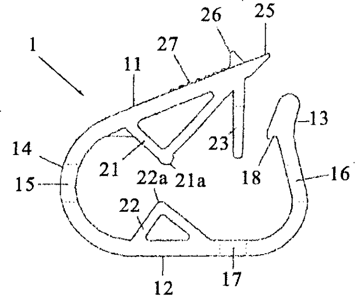
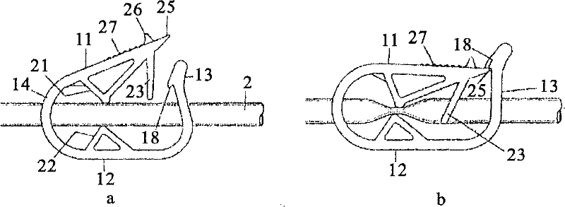
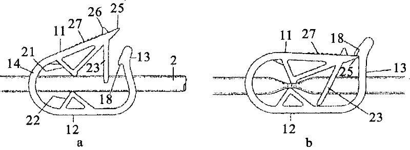
[0041] The present invention will be specifically described below with reference to the drawings, but the present invention is not limited to the specific examples described below. figure 1 It is a side view showing the clamp device of the present invention. exist figure 1 Among them, the clamping device of the present invention connects the upper end portion 11, the bent portion 14 provided with the pipe insertion hole 15, the bottom portion 12, and the standing end portion 13 provided with the pipe insertion hole 16, and the front end portion of the upper end portion 11 has a locking protrusion 25 . On the other hand, on the front end side of the standing end portion 13, there is a locking groove portion 18 inside, and the locking groove portion 18 is detachably engaged with the above-mentioned locking protrusion portion 25 to form an annular body. Inside the annular body, there is a first protruding portion 21 extending downward under the upper end portion 11 , and a seco...


PUM


Abstract

The invention provides a well-qualified clamping device which presses, with high operational efficiency, a clamping tube in one operation in a manner of preventing the tube from transverse deviation, avoids deviation at the time of engagement between a locking projecting portion and a locking groove portion, and improves rate of finished products and shortens finishing period by reducing cost of moulds so as to realize reduction of the cost. In the clamping device of the invention, inner sides of an upper end (11) and a bottom (12) include a first projecting portion (21) and a second projecting portion that are opposite to each other, and also includes a downwards-extending pressing portion (23) nearby, a front end (24) of the pressing portion (23) is formed with square or quadrate projections (23a), (23b) in a crotched manner. Further, the bottom (12) in an extending direction of the pressing portion (23) includes a incision portion (17).

Description

technical field [0001] The present invention relates to a clamping device capable of clamping a tube in one operation, correcting and preventing the lateral deviation of the tube while clamping the tube, and preventing the clamping protrusion and the clamping groove from The offset of the two locking parts at the same time is the so-called one-time operation clamping device. Background technique [0002] The conventional clamping device is used as a fluid switching device for stopping or flowing a fluid such as blood or medical solution flowing in a tube such as a blood circuit tube or a blood transfusion tube. Especially in the blood circuit, since the clamping device is used for various purposes depending on the type of the tube diameter, the clamping device produces a tube deviation during use, and when the tube is blocked, it is extruded from the clamping part, so that the clamping device Insufficient occlusion. In addition, as the engagement protrusion and the engagem...

Claims


Application Information

Patent Timeline
Patent Type & Authority Patents(China)
IPC IPC(8): A61M5/168A61M5/175A61M39/28
Inventor 安田良隆古川幸久驹宫哲司
Owner HANACO MEDICAL CO LTD
Learn More