Self-tension cloth storage device

A cloth storage device and tension technology, applied in the direction of processing textile material carriers, etc., can solve the problems of slow cloth storage process, cumbersome hydraulic mechanism operation, cloth shrinkage, etc., and achieve the goal of solving shrinkage problems, improving stability, and increasing cloth storage speed Effect

Active Publication Date: 2009-01-28
ANHUI ANLI MATERIAL TECH
View PDF0 Cites 13 Cited by
  • Summary
  • Abstract
  • Description
  • Claims
  • Application Information

AI Technical Summary

Problems solved by technology

Therefore, when the fabric is connected, in order to ensure the tension of the fabric behind, the valve opening of the oil return valve 7 is relatively small. At this time, the oil pressure of the oil return is relatively high, and the tension of the fabric is also large, causing the fabric to shrink; Independent action, slow cloth storage process; the operation of the hydraulic mechanism is cumbersome, and the valve of the oil return valve 7 needs to be adjusted from time to time

Method used


Image

  • Self-tension cloth storage device
  • Self-tension cloth storage device
  • Self-tension cloth storage device

Examples


Embodiment Construction

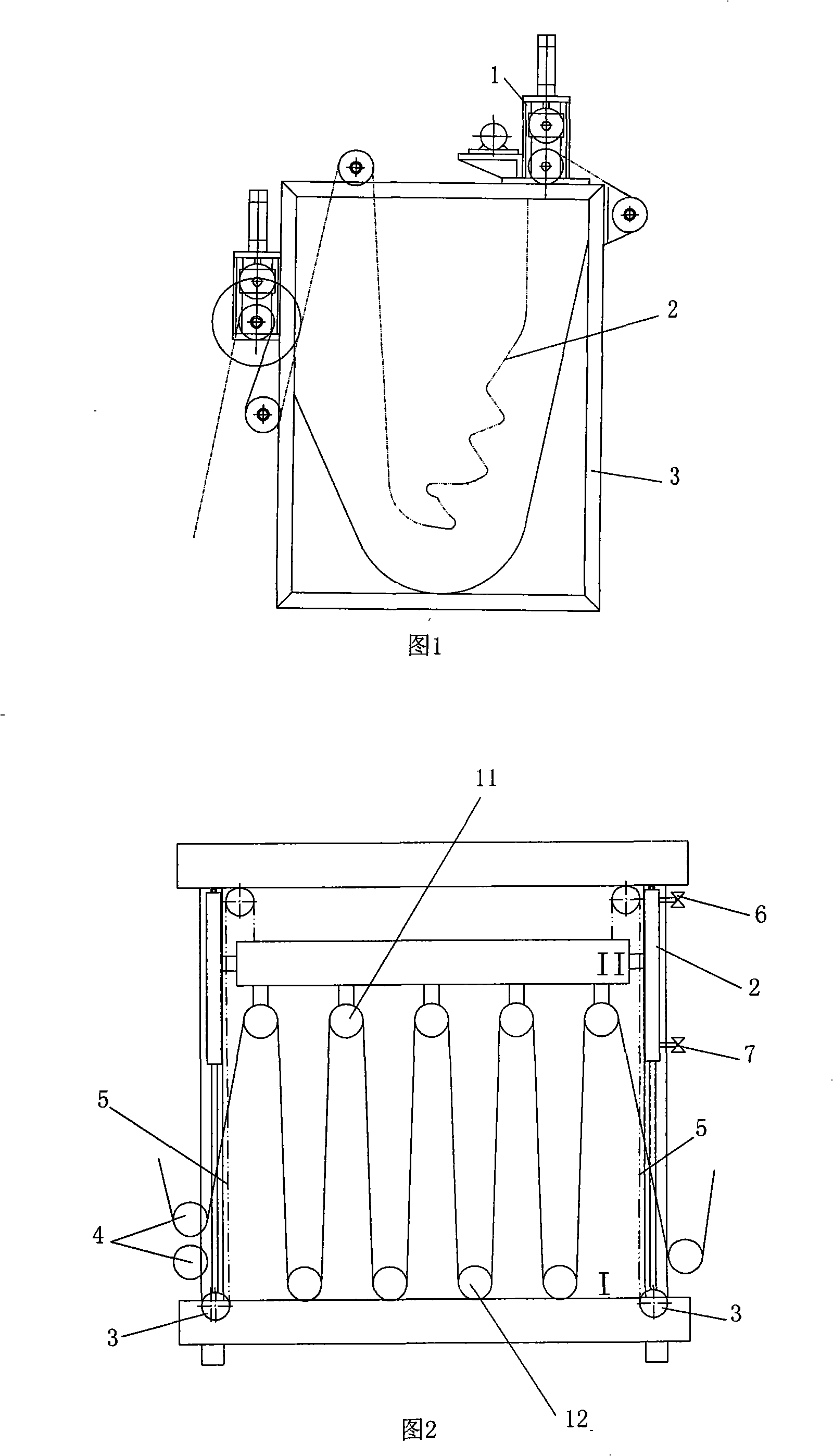
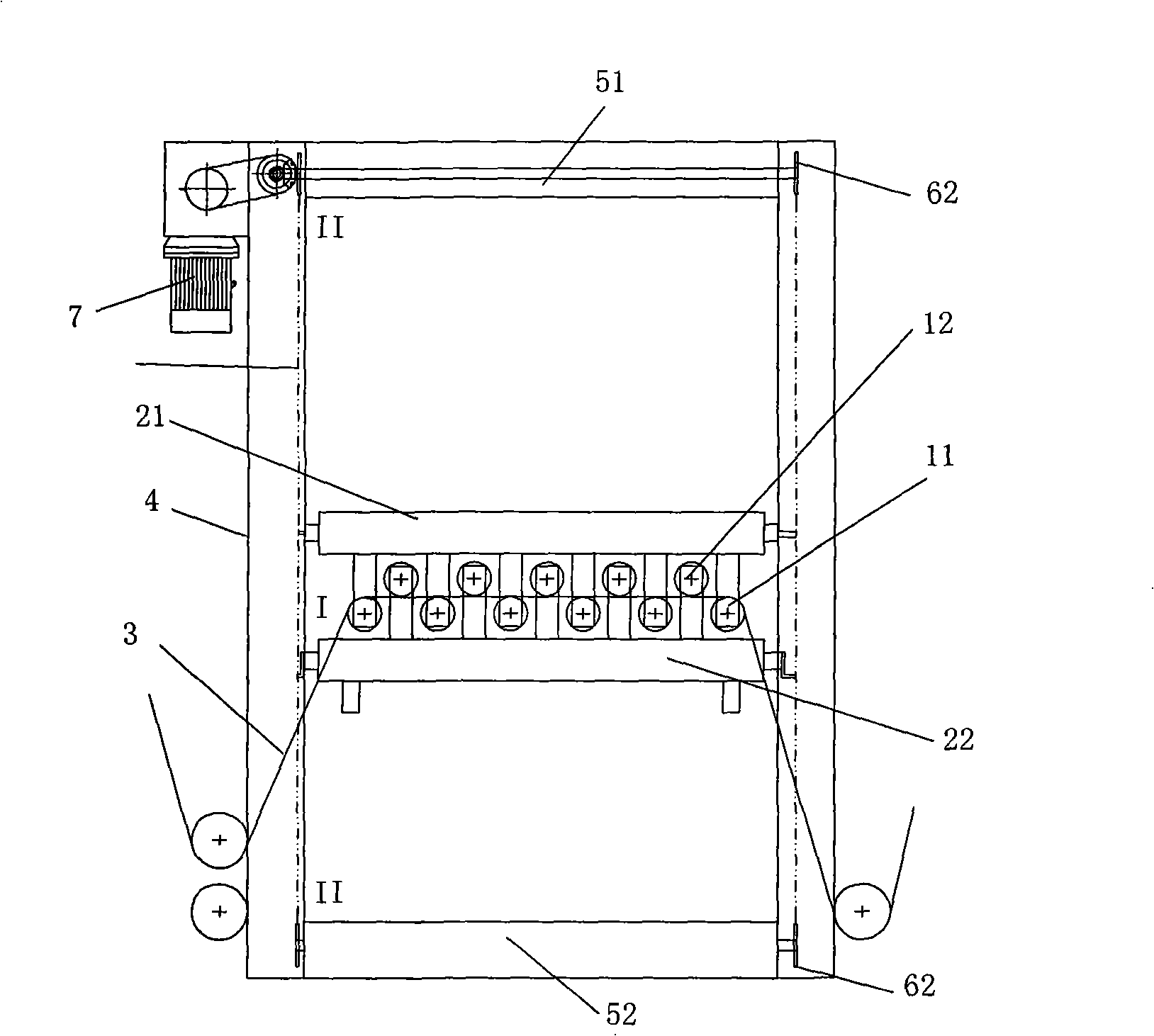
[0024] Referring to Fig. 3(a), the upper row of rollers 11 and the lower row of rollers 12 are arranged oppositely, and the fabric 3 is led out alternately in a "Z" shape on the upper row of rollers 11 and the lower row of rollers 12.

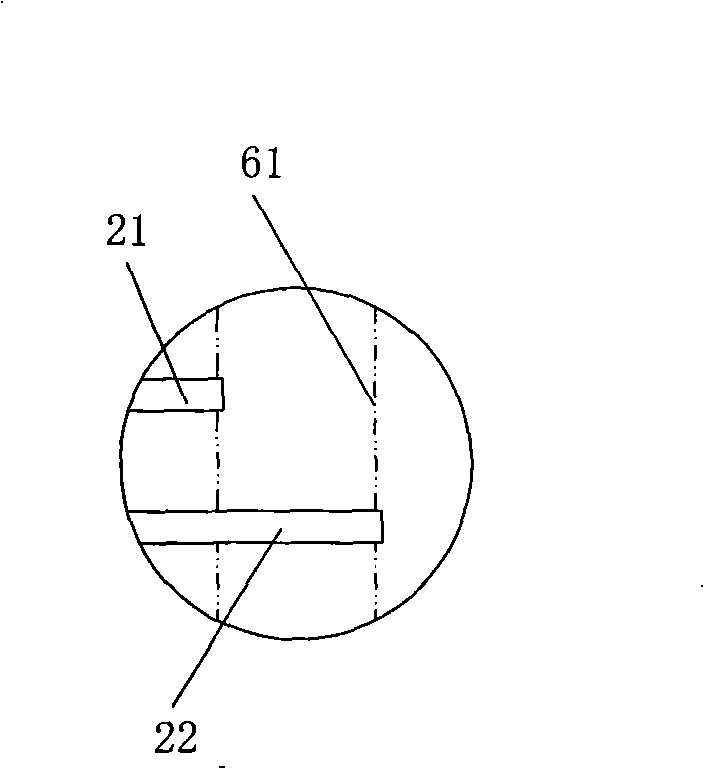
[0025] As shown in Figure 3 (a), in this embodiment, a transmission structure is arranged in a rectangular frame in the cloth storage box 4, and the top frame and the bottom frame of the rectangular frame are respectively the top rod 51 and the bottom of which are provided with sprockets 62 at both ends. Rod 52, the two sides of the rectangular frame are annular transmission chains 61, the annular transmission chain 61 and the sprockets 62 at the corresponding positions of the top rod 51 and the bottom rod 52 constitute a chain sprocket transmission structure, and the upper row of roller frames parallel to each other 21 and the lower row of roller frames 22 are respectively hung on the drive chain 61 at their respective ends, and the upper row o...


PUM


Abstract

The invention provides a cloth accumulator with self tension, which is provided with upper rollers and lower rollers reversely. The cloth moves in a Z-shaped way alternately on the upper and the lower rollers. The cloth accumulator with self tension is characterized in that: a transmission mechanism is arranged in a cloth storage box in rectangular frame shape; the top frame and the bottom frame of the rectangular frame are provided with a top rob and a bottom rob that are provided with sprocket wheels respectively; an annular gearing chain which forms the chain and sprocket transmission mechanism with the sprocket wheels which are positioned at the corresponding positions of the ends of the top and the bottom robs is arranged on the frames at the two sides of the rectangular frame. An upper roller shelf and a lower roller shelf are hung and arranged at the different sides of the annular gearing chain to form reverse movement between the upper roller shelf and lower roller shelf. The invention can solve not only the problem of tension in the consecutive production process of the cloth, but also the constriction problem of the textiles in production, thus improving the cloth accumulating speed and simplifying the operation process.

Description

technical field [0001] The invention relates to a cloth storage device used in printing, dyeing and textile industries for ensuring continuous production of production lines. Background technique [0002] In the printing and dyeing and textile industries, the cloth accumulator is a necessary equipment for the production line to ensure continuous production. [0003] At present, the commonly used cloth storage devices have two structural forms, including: [0004] The working principle of the J-type cloth storage device shown in Figure 1 is that if the cloth needs to be connected during the production process, the counter-rotating roller 1 is manually started quickly. Under the action of the frictional force of the counter-rotating roller 1, the cloth storage box 3 quickly A J-shaped stocker 2 is formed. This form causes the J-type cloth storage 2 to lose tension in the subsequent production, thus resulting in unstable production. [0005] Figure 2 shows a cloth storage de...

Claims


Application Information

Patent Timeline
Patent Type & Authority Applications(China)
IPC IPC(8): D06B23/04
Inventor 杨滁光姚和平葛伦年张小平陆伟
Owner ANHUI ANLI MATERIAL TECH
Why Eureka
Try Eureka