City track traffic U type beam

An urban rail transit, U-shaped technology, applied to bridges, buildings, etc., can solve the problems of unsafe walking and poor safety protection for maintenance personnel, and achieve the effects of reducing noise pollution, high space utilization, and reducing the height of the structure

Active Publication Date: 2009-01-28
BEIJING URBAN CONSTR DESIGN & DEV GRP CO +1
View PDF1 Cites 14 Cited by
  • Summary
  • Abstract
  • Description
  • Claims
  • Application Information

AI Technical Summary

Problems solved by technology

[0003] The purpose of the present invention is to provide a U-shaped beam for urban rail transit, to solve the problems of reducing the material consumption of U-shaped components, impr

Method used


Image

  • City track traffic U type beam
  • City track traffic U type beam
  • City track traffic U type beam

Examples


Embodiment 1

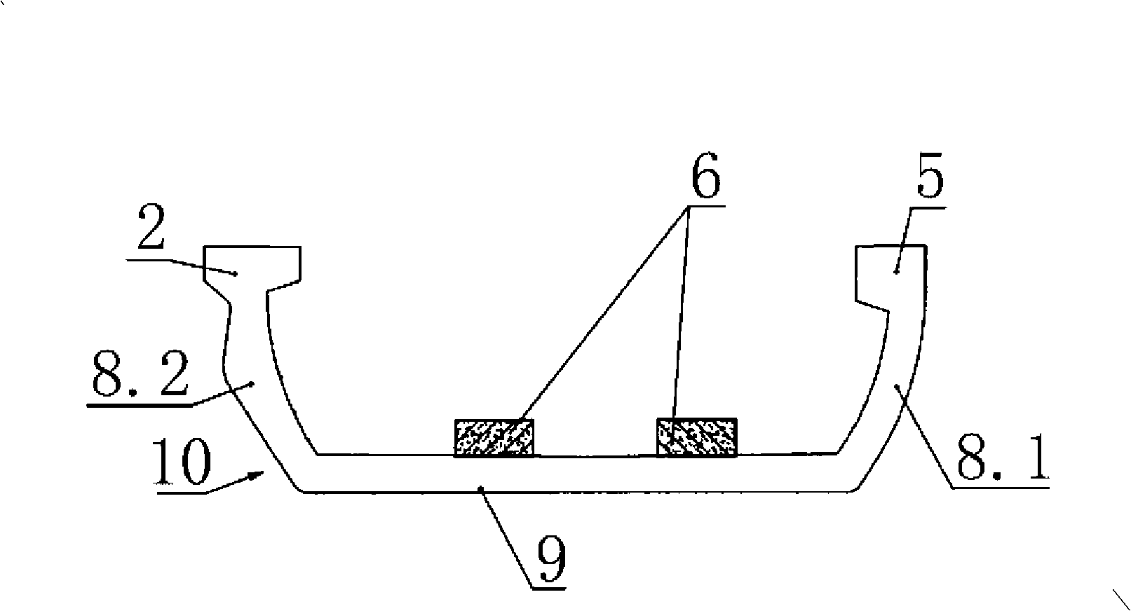
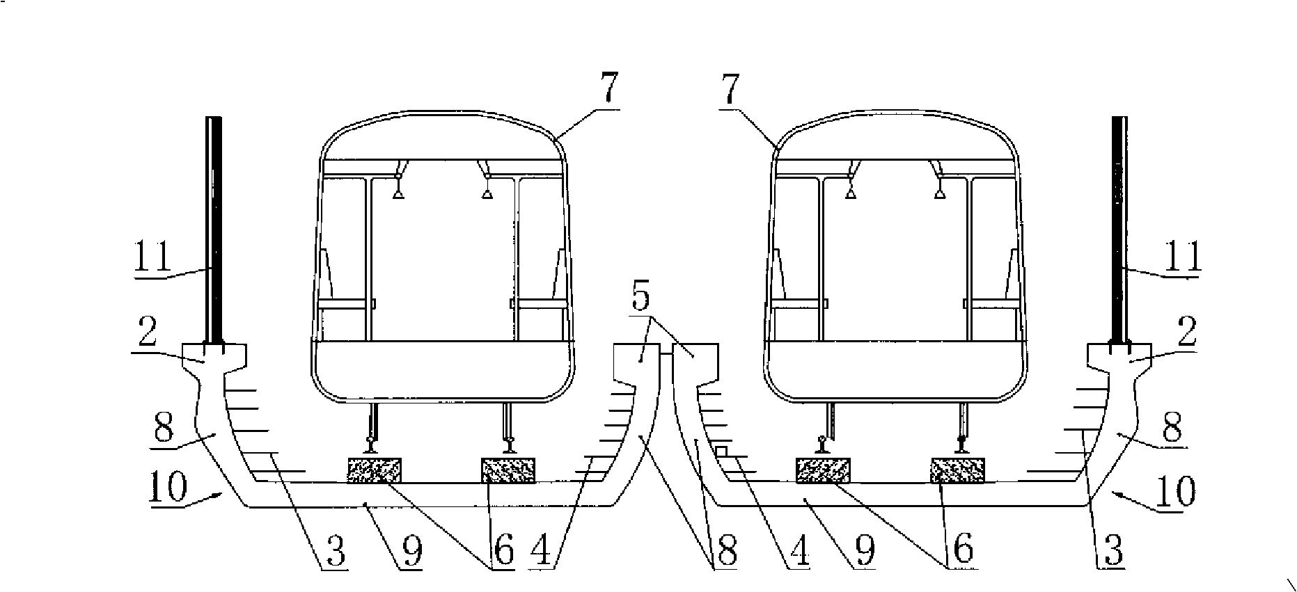
[0028] Embodiment one sees figure 1 , figure 2 , image 3 , as shown, in this U-shaped beam of urban rail transit, the beam body 10 is connected by the bottom plate 9, the webs 8 on both sides and the flange plate on the top of the web to form a U-shaped cross-section channel, and the upper surface of the bottom plate 9 is connected to the bearing The rail platform 6 and the train 7 run on the rail platform 6. The power supply device, the power supply cable support body 3 and the communication signal cable support body 4 are fixedly connected along the beam body lengthwise. concrete structure. The webs 8 on both sides are asymmetrical, one side of which is a curved web 8.1 with equal wall thickness, and the flange plate connected to the top of the side web is a 7-shaped flange plate 5, that is, only the inward Flange; the other side is the convex, smooth and thickened curved web 8.2 with unequal wall thickness on the outside of the middle and upper section, and the flange ...

Embodiment 2

[0030] Embodiment two see Figure 4 , and the difference from the first embodiment is that the power supply device is a three-rail power supply device 12 provided on the base plate 9 .

Embodiment 3

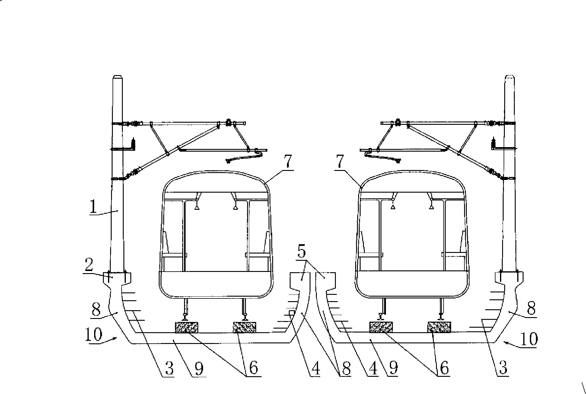
[0031] Embodiment three see Figure 5 , Image 6 , The U-shaped beam is a double U parallel shape, and the double U-shaped beams share the same bottom plate. The U-shaped beam and the cover beam 13 are connected as a whole. The catenary column 1 is placed on the T-shaped flange plate 2 . The communication signal cable support body 4 is located between two pairs of rail platforms 6 .


PUM


Abstract

The invention discloses a U-shaped girder for urban rail traffic. A girder body is connected into a channel with a U-shaped section by a bottom plate, web plates on both sides and flange plates at the top of the web plates. The upper surface of the bottom plate is connected with a support rail platform, a power supply device, a power supply cable bearing body and a communication signal cable bearing body are fixedly connected along the length direction of the girder body, the web plates on both sides are asymmetric, wherein, a bending arc even wall thickness web plate is on one side and the flange plate connected with the top of the side web plate is a 7-shaped flange plate, namely, only an inward flange is arranged; a smooth and thickness-adding bending arc non-even wall thickness web plate with the exterior of medium-and-upper-sections thereof being prominent is on the other side, and the flange plate connected with the top of the web plate is a T-shaped flange plate, namely, an internal flange and an external flange are arranged. The girder can save materials and improve the torsion resistance capacity of an opening thin-wall U-shaped girder. By utilizing the bottom plate to support the rails and trains, the girder reduces the standard height of the rails and the entire height of a bridge, diminishes the impact on the surrounding environment, and prevents the trains from running out of the bridge after running off rails. The girder is applicable to medium-span bridges with the height of about 30 meters for the urban rail traffic.

Description

technical field [0001] The invention relates to a viaduct track bed supporting member for supporting rails. Background technique [0002] Traditional viaducts generally use top-supporting box-section members or T-section members to support the track. The disadvantages are that the overall height of the building is large and the space utilization rate is low, which not only has a great impact on the urban landscape, but also creates a sense of depression for people on the ground. , and it is easy to cause noise disturbance to nearby residents. Moreover, if the train derails, the train will easily rush out of the bridge, causing harm to surrounding buildings and people. Known U-shaped beams, such as the Chinese patent application whose publication number is CN 101120140A and titled "U-shaped spans for railway tracks", have a symmetrical beam body with equal-wall thickness webs on both sides. Net column and sound insulation barrier, it is necessary to increase the wall thickn...

Claims


Application Information

Patent Timeline
IPC IPC(8): E01D2/00
Inventor 宋敏华朱自强杨秀仁陈光阙孜佘才高朱悦明许建军任静许巧祥刘立黎庆白唐瀛张伟刘运亮王奕然张晓林王云尹晓李文会王峰康文峰王进张丁军刘继兵汪永新刘静文周岩朱智勇祝岚王怀良王胜许利民朱晨陈亮王箭
Owner BEIJING URBAN CONSTR DESIGN & DEV GRP CO
Why Eureka
Try Eureka