Antifreeze fluid built-in type differential pressure transfer control valve

A built-in, control valve technology, applied in the valve's device for absorbing fluid energy, lift valve, valve details, etc., can solve the problem of valve freezing, affecting the safety of liquid supply and automation, and user loss, etc., to eliminate The effect of liquid strike and automatic control of sealing and non-return without external power

Active Publication Date: 2009-01-28
TIANJIN GUOWEI FEEDING & DRAINAGE EQUIP MENT MFG
View PDF0 Cites 10 Cited by
  • Summary
  • Abstract
  • Description
  • Claims
  • Application Information

AI Technical Summary

Problems solved by technology

However, because the control chamber of the valve is full of liquid and does not flow when it is not in motion, it is very easy to be frozen in winter when there is no heating measure outdoors and indoors, so that the valve cannot operate, and even the valve is cracked by freezing.
[0003] This type of valve is to push the valve stem to open and close by controlling the water in and out of the upper and lower chambers of the chamber. If there is no water in the upper and lower chambers, the entire valve cannot move and loses its function. If the control system is damaged due to other reasons, the pump will reverse, a large amount of water will be lost, and there will be serious liquid shock. There will be serious accident hazards, which will affect the safety and automation of the liquid supply, and bring losses to the user. This problem has become a real problem that the industry has not yet solved but has to face

Method used


Image

  • Antifreeze fluid built-in type differential pressure transfer control valve
  • Antifreeze fluid built-in type differential pressure transfer control valve
  • Antifreeze fluid built-in type differential pressure transfer control valve

Examples


Embodiment Construction

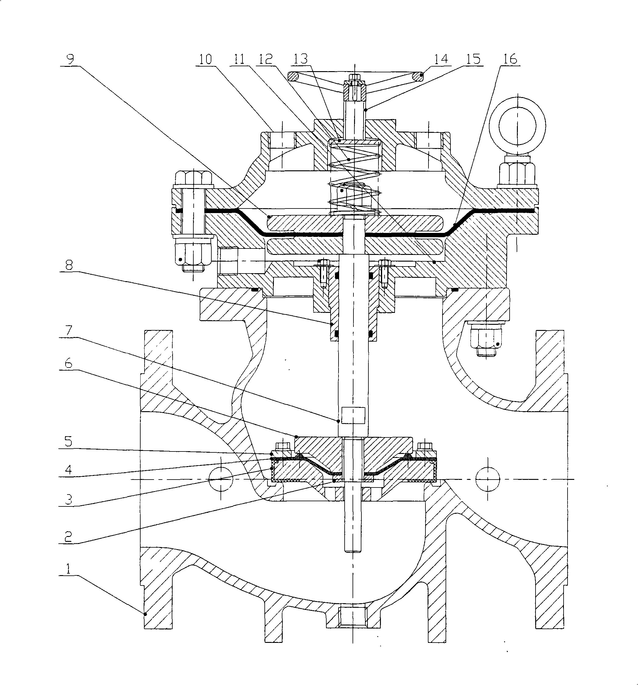
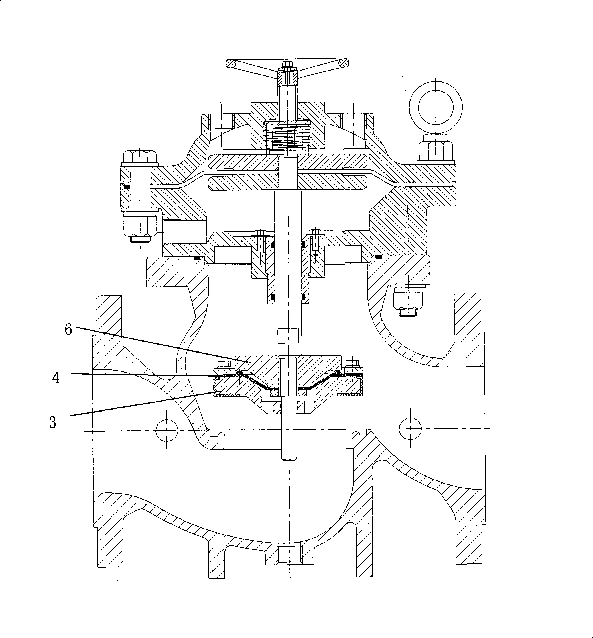
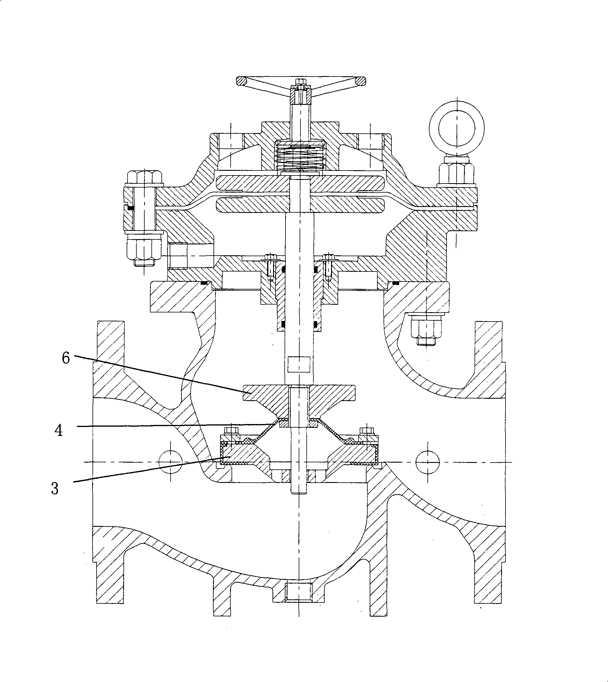
[0016] The structure of the antifreeze fluid built-in differential pressure transmission control valve of the present invention will be described in conjunction with the accompanying drawings and embodiments.

[0017] Such as figure 1 As shown, the antifreeze type fluid built-in differential pressure transmission control valve of the present invention is composed of a valve body and a valve core. The valve body includes a hand wheel 14, a screw rod 15, an upper valve cover 10, a lower valve cover 11, and a valve body 1. The spool includes a backing plate 9, a valve stem 7, a small valve plate 6, a lower diaphragm 4, and a large valve plate 3. When the pump is turned on, the gate can be closed and opened slowly. When the pump is stopped, because there is a flexible connection lower diaphragm 4 with holes between the small valve plate 6 and the large valve plate 3, the pressure relief of the backflow liquid can be realized, and pressure can be generated. Poor, drive the valve t...


PUM


Abstract

The invention provides an anti-freezing liquid interior pressure difference transfer control valve which comprises a valve body and a valve core comprising a control chamber. The valve core part moves vertically along a valve lever shaft in the valve body. The valve body comprises a handwheel, a screw, an upper valve cover and a lower valve cover and is provided with a liquid inlet, a liquid outlet and a middle opening that are communicated; the middle opening of the valve body is connected with the bottom of the lower valve cover in a sealing manner, the axis of the liquid inlet of the valve body and the axis of the liquid outlet are distributed at a certain angel; the valve core comprises a pair of liners of the same shape, a lower patch, a seal sleeve, a valve lever, a large valve plate, a lower patch and a small valve plate, wherein, the valve lever can move freely relative to the central direction of a sealing opening at the middle of the main valve body. The transfer control valve has the advantages that the control valve is especially suitable for the working environment with an external temperature of the valve lower than 0 DEG C; when a pump is started, a sluice is closed and the valve is opened slowly strictly according to the operation rules of the pump, and when the pump is stopped, the large valve plate is first closed, keyholes at the circumference of the small patch are relieved from pressure, the small valve plate and the valve lever are pulled slowly downward to be closed; therefore, the control valve is not afraid of freezing environment, completely removes liquid breakdown and fulfills automatic control and sealing non-return without an external motive force.

Description

technical field [0001] The invention relates to an antifreeze type fluid built-in differential pressure transmission control valve for completely eliminating liquid shock at the pump outlet, especially a control valve that can realize automatic control and sealing check without external power and is suitable for use in any working conditions in winter Antifreeze fluid built-in differential pressure transmission control valve. Background technique [0002] Existing known control valve is made of upper bonnet, lower bonnet, valve body, connecting bolt, fastening bolt, the 1st outer bypass passage member, the 2nd outer bypass passage member and spool, it is like this Working: That is, before the valve is closed, the pressure liquid has entered the upper and lower chambers of the control chamber through the connecting pipe, so that the opening and closing of the valve are in the preset working condition. When the pump is turned on, the valve plate opens slowly, the liquid in th...

Claims


Application Information

Patent Timeline
Patent Type & Authority Applications(China)
IPC IPC(8): F16K17/30F16K1/36F16K27/00F16K1/48F16K47/02F16K31/126F16K41/00
Inventor 刘永刘庆
Owner TIANJIN GUOWEI FEEDING & DRAINAGE EQUIP MENT MFG
Why Eureka
Try Eureka