
Reversing valve

A technology of switching valve and locking element, applied in the field of switching valve, can solve problems such as leakage and sealing

Active Publication Date: 2009-01-28
KRAUSSMAFFEI TECH GMBH
View PDF0 Cites 2 Cited by
  • Summary
  • Abstract
  • Description
  • Claims
  • Application Information

AI Technical Summary

Problems solved by technology

Furthermore, due to the dynamic sealing, there are leak-tightness problems in known diverter valves which lead to leakage

Method used


Image

  • Reversing valve

Examples


Embodiment Construction

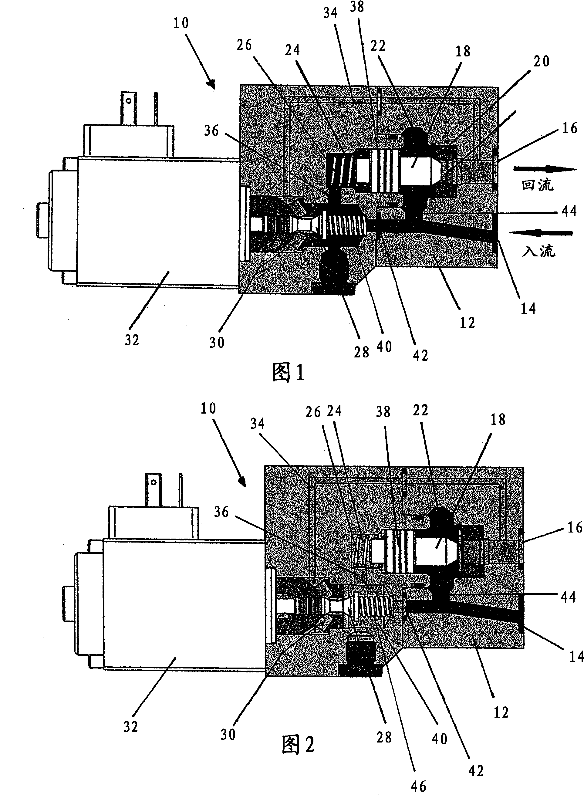
[0021] The switching valve 10 shown in FIGS. 1 and 2 includes a housing 12 which, for better assembly, can be designed in two parts, as shown in FIGS. 1 and 2 . An inlet 14 and an outlet 16 are shown in the housing 12 . Fluid (inflow) from a high pressure source (dosing device) merges into the inlet 14 . Pressures in the range up to 250 bar and higher occur here. The return flow is connected to a mixing head, not shown here. The pressure in the reflux can vary within a range from a pressure level slightly lower than that of the inflow up to a few bar range (eg 8 bar).

[0022] A chamber is formed in the housing 12, in which chamber a reciprocating movement (to the left and right in FIGS. 1 and 2) is accommodated a lock valve 18 on which a piston 38 is integrally formed. In this case, the piston 38 is dimensioned in such a way that it closes the chamber in a wall-tight manner, so that a variable-sized active chamber is formed on both sides of the piston 38 . The first activ...


PUM


Abstract

The invention relates to a reversing valve, in particular for opening and shutting off a mixing head. Said valve comprises a housing (12) that is equipped with a fluid supply (14) and a fluid drain (16) and a blocking element (18), which co-operates with a seat (20) in the vicinity of the fluid drain (16) in such a way that when said blocking element (18) is placed against the seat (20), a flow path between the supply (14) and the drain (16) is sealed and when the blocking element (18) is raised from the seat (20), the flow path between the supply (14) and the drain (16) is opened. The blocking element (18) has a plunger (38), either side of which is provided with a first working chamber (24) and a second working chamber (22) that may be filled with the fluid. The aim of the invention is to ensure a functionally reliable reversing process, even when small drives are used. To achieve this, the valve is equipped with a pilot stage (28, 30, 40, 44) comprising a switching element (28) and said pilot stage (28, 30, 40, 44) is configured and connected to the supply (14) and drain (16), in addition to the two working chambers (22, 24), in such a way that in a first switching state of the switching element (28) the pressure from the supply (14) prevails in both working chambers of the plunger (38) and in a second switching state of the switching element (28), the pressure from the supply (14) prevails in the second working chamber (22) of the plunger (18) and the pressure from the drain (16) prevails in the first working chamber (24).

Description

technical field [0001] The invention relates to a switching valve, in particular for switching a mixing head on and off. Such valves are used, for example, when several mixing heads are operated on a metering machine, wherein only one mixing head is always selected for operation. The other mixing heads are switched off during this time period. Background technique [0002] In order to avoid malfunctions, the basic prerequisite is absolute tightness of such switching valves. When a diversion valve can leak, it creates a loss of flow at the other mixhead, which in turn leads to waste. [0003] Currently, switching valves of this type are used in which a switching device is provided in the form of a valve element which bears against the valve seat or which can be lifted from the valve seat. When the valve element bears against the valve seat, the flow path from the inlet connected to the container to the outlet connected to the mixing head is interrupted. When the valve ele...

Claims


Application Information

Patent Timeline
Patent Type & Authority Applications(China)
IPC IPC(8): F16K31/124
CPCF16K31/423F16K27/00F16K31/124
Inventor W·泽希蒂格
Owner KRAUSSMAFFEI TECH GMBH
Learn More