Image processing device
An image processing device, image signal technology, applied in image communication, solid image signal generator, signal generator with a single pick-up device, etc., can solve the problems of low frequency response characteristics, lower resolution of colored parts, etc.
- Summary
- Abstract
- Description
- Claims
- Application Information
AI Technical Summary
Problems solved by technology
Method used
Image

Examples
no. 1 approach
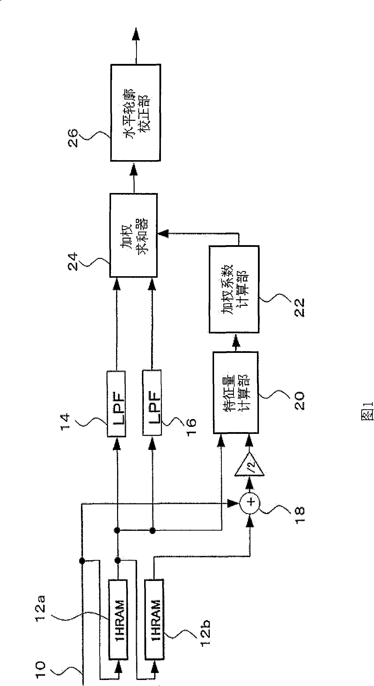
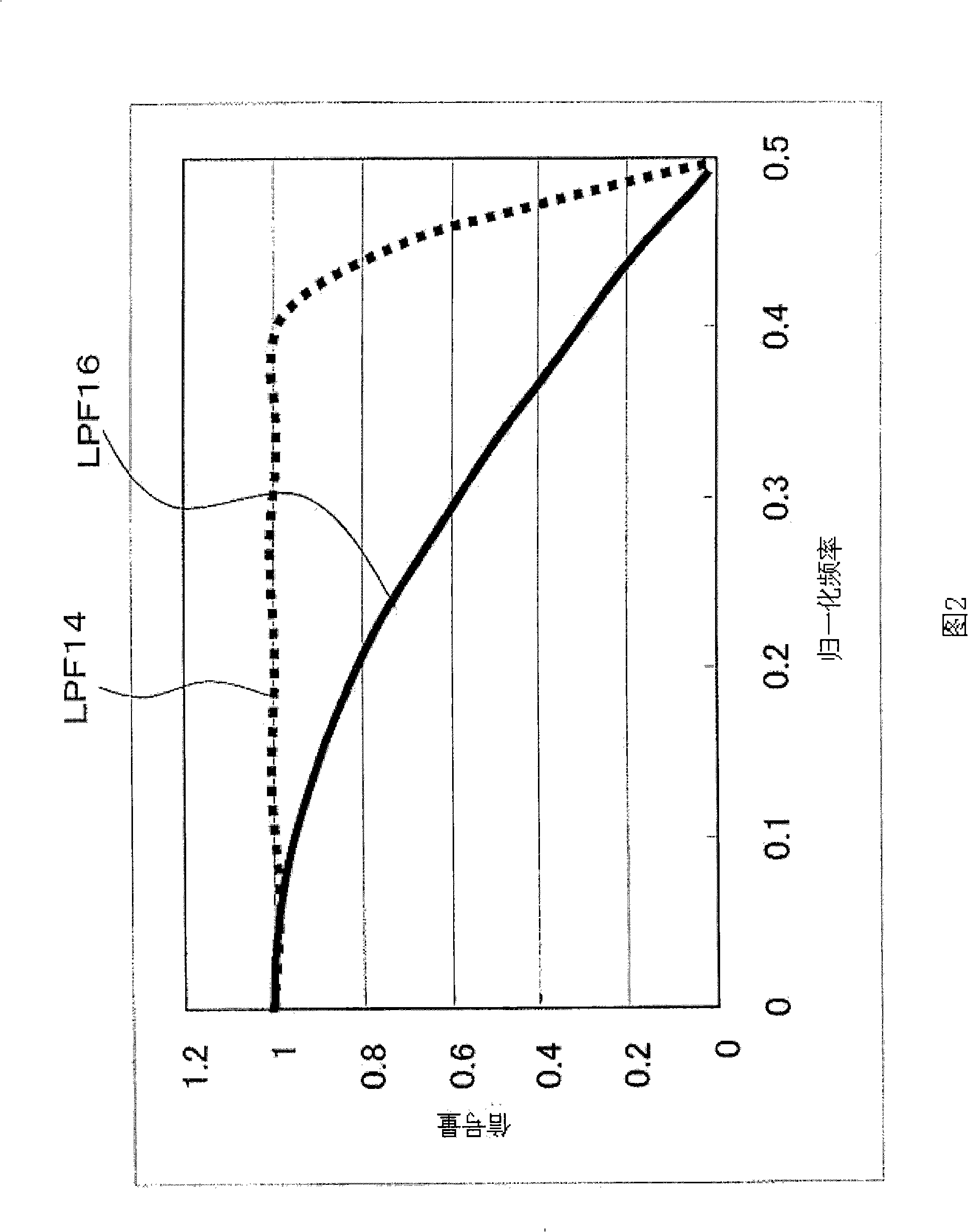
[0036] FIG. 1 is a block diagram showing the configuration of an image processing device according to a first embodiment of the present invention. The image processing device includes an image signal input unit 10 , 1HRAM 12 a , 12 b , LPF 14 , 16 , a summer 18 , a feature quantity calculation unit 20 , a weight coefficient calculation unit 22 , a weighted summer 24 , and a horizontal contour correction unit 26 .
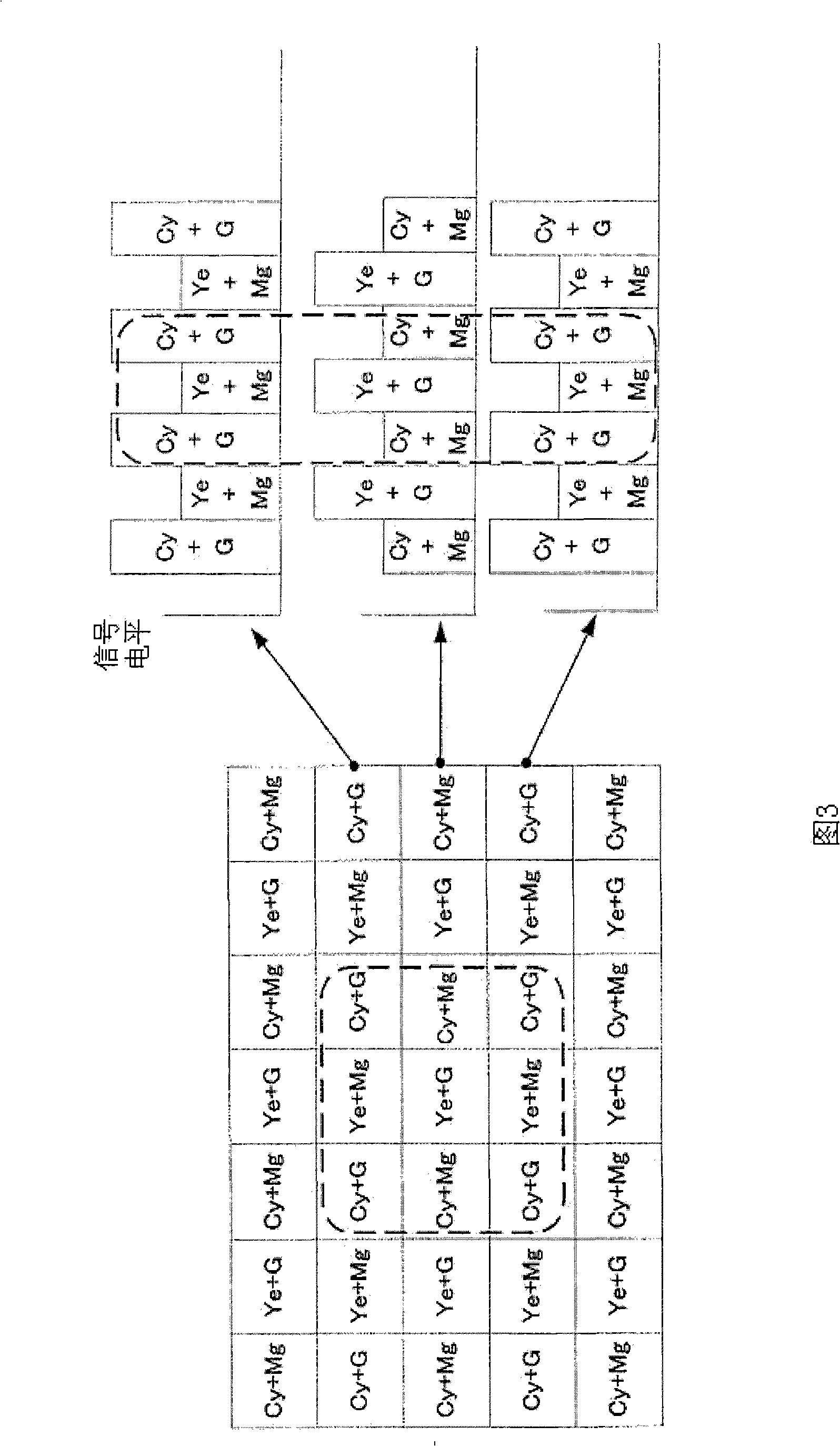
[0037] In the field read signal input from the image signal input section 10, a mixed signal of Cy (cyan) and Mg (magenta) and a mixed signal of Ye (yellow) and G (green) are alternately arranged in the (n) row, and Cy Mixed signals of (cyan) and G (green) and mixed signals of Ye (yellow) and Mg (magenta) are alternately arranged in the (n+1) row. As the image signal, a signal obtained by adding CDS / analog gain to the output signal of the imaging element and then AD-converted may be input directly, or an image signal previously recorded in a memory device may be seq...
no. 2 approach
[0056] 4 is a block diagram showing the configuration of an image processing device according to a second embodiment. The image processing device of the second embodiment has the same basic configuration as that of the image processing device of the first embodiment, except that a plurality of LPFs 16a to 16c having the same characteristics are provided. Furthermore, the image processing device of the second embodiment includes a vertical LPF (hereinafter referred to as “VLPF”) 28 and a weighted adder 30 .
[0057] The plurality of LPFs 16a to 16c receive the signal from the image signal input unit 10 and the output signals of the 1HRAMs 12a and 12b, and apply low-pass filter processing to the signals of the plurality of lines, respectively. LPF16a~16c is composed of (1+Z -1 ) / 2, sacrificing the frequency response characteristics and reducing the amount of spurious signals in the color boundary. However, even (1+Z -1 ) / 2 LPF also cannot eliminate artifacts in color boundari...
no. 3 approach
[0066] 6 is a block diagram showing the configuration of an image processing device according to a third embodiment of the present invention. The image processing device of the third embodiment has the same basic configuration as that of the image processing device of the second embodiment, and the third embodiment further includes an LPF 32 and a weighted adder 34 .
[0067] LPF32 for example has (1+3Z -1 +3Z -2 +Z -3 ) / 8 tap structure. Compared with LPF14 and LPF16a to 16c, LPF32 has a lower frequency response characteristic, and has a characteristic of suppressing false signals on color boundaries better than LPF14 and LPF16a to 16c.
[0068] In the third embodiment, the weighting coefficient calculation unit 22 calculates the weighting coefficients k and k2 and also calculates the weighting coefficient k3 used by the weighted adder 34 .
[0069] As described above, artifacts that become vertical stripes generated in a border with a hue of yellow or cyan cannot be reduc...
PUM
 Abstract
Description
Claims
Application Information
 - R&D
- Intellectual Property
- Life Sciences
- Materials
- Tech Scout
- Unparalleled Data Quality
- Higher Quality Content
- 60% Fewer Hallucinations
Browse by: Latest US Patents, China's latest patents, Technical Efficacy Thesaurus, Application Domain, Technology Topic, Popular Technical Reports.
© 2025 PatSnap. All rights reserved.Legal|Privacy policy|Modern Slavery Act Transparency Statement|Sitemap|About US| Contact US: help@patsnap.com