No-axle spiral conveyer

A shaftless screw conveying and casing technology, applied in packaging and other directions, can solve the problem that bearings and reducers are easily affected by high temperature

Inactive Publication Date: 2009-02-04
钱尧翎
View PDF0 Cites 1 Cited by
  • Summary
  • Abstract
  • Description
  • Claims
  • Application Information

AI Technical Summary

Problems solved by technology

[0002] The current common screw conveyors include motors, casings, transmission shafts pierced on the casings, head bearings installed in bearing seats, and reducers. Among them, the head bearings are installed in the casing, and the installation and removal All the internal bearings need to open the casing first, and if the high-temperature materials are transported in the application, the bearings and the reducer are easily affected by high temperature

Method used


Image

  • No-axle spiral conveyer
  • No-axle spiral conveyer

Examples


Embodiment Construction

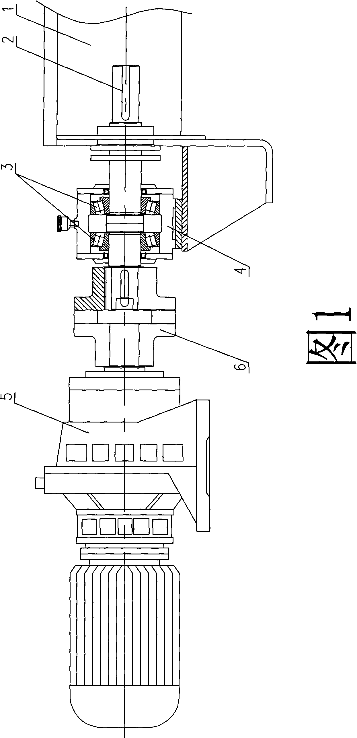
[0011] A shaftless screw conveyor of the present invention comprises a casing 1, a transmission shaft 2 pierced on the casing 1, a head bearing 3 installed in a bearing seat 4 and a reducer 5, the head bearing 3 is set On the transmission shaft 2 protruding out of the casing.

[0012] As shown in Figure 1, it is embodiment 1, the transmission shaft 2 and the reducer 5 are connected by a coupling 6, and the head bearing 3 is installed on the transmission shaft 2 outside the casing, wherein the head bearing 3 is a pair For radial roller bearings, there are bearing baffles and oil seals at both ends of the bearing.

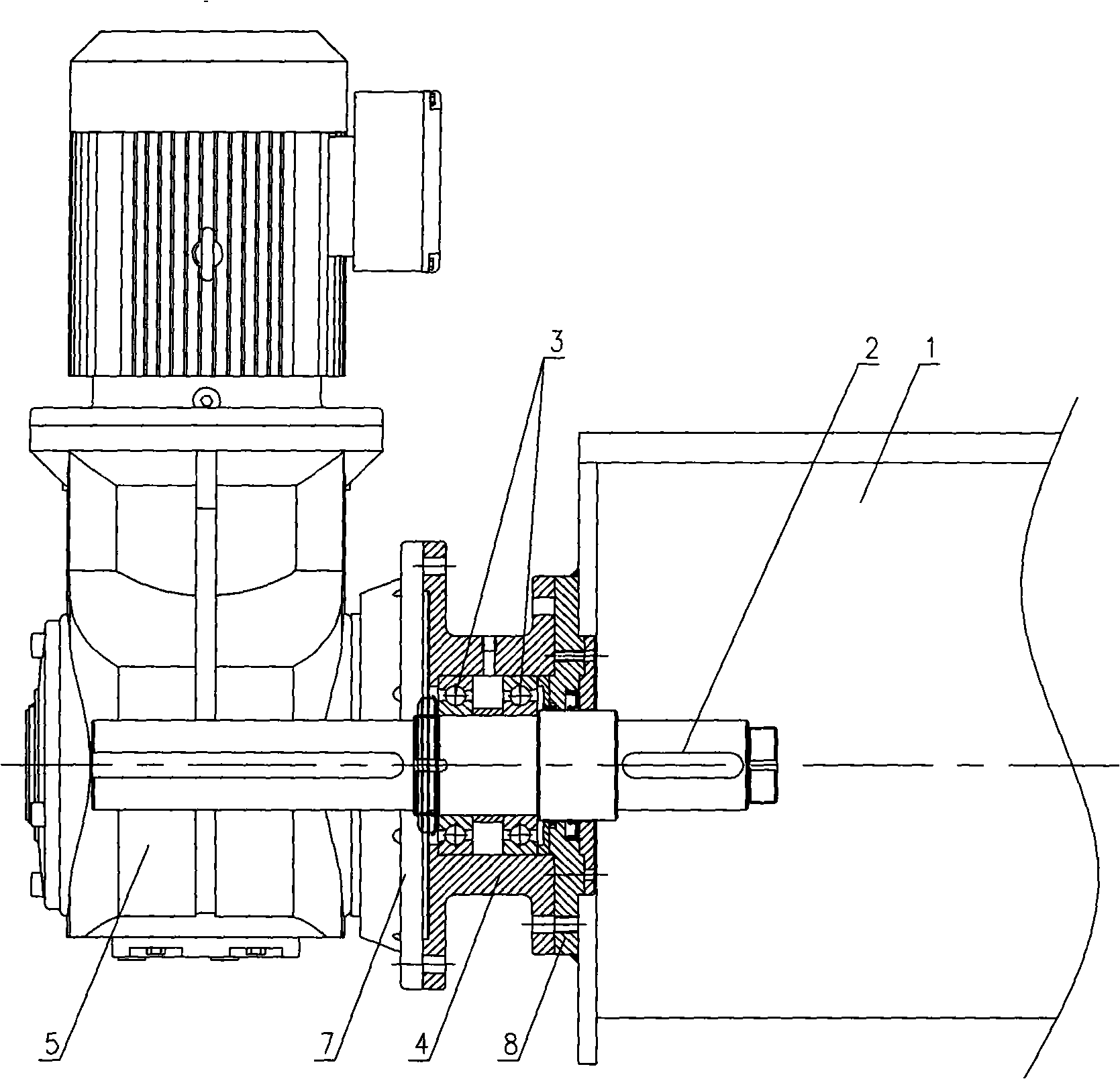
[0013] Such as figure 2 Example 2 is shown, the reducer 5 is connected to the bearing seat 4 through the flange 7, and the bearing seat 4 is connected to the casing 1 through the flange 8, wherein the head bearing 3 is a pair of radial ball bearings. The structure also has sealing and dust-proof functions, and is suitable for conveying materials with high water con...


PUM


Abstract

The invention discloses a no-shaft spiral conveying machine, comprising a shell, a transmission shaft which passes through the shell, a head bearing and a reducing machine which are arranged inside a bearing seat; the head bearing is arranged on the transmission shaft which extends out of the shell; by adopting the technical proposal, the head bearing is arranged outside the shell, the shell is not needed to be opened when the head bearing is assembled and disassembled; furthermore, the bearing and the reducing machine are affected little by the high temperature and are suitable for conveying high-temperature material.

Description

technical field [0001] The invention relates to a shaftless screw conveyor. Background technique [0002] The current common screw conveyors include motors, casings, transmission shafts pierced on the casings, head bearings installed in bearing seats, and reducers. Among them, the head bearings are installed in the casing, and the installation and removal All the internal bearings need to open the casing first, and if the high-temperature materials are transported in the application, the bearings and the reducer are easily affected by high temperature. Contents of the invention [0003] The technical problem to be solved by the present invention is to provide a shaftless screw conveyor which is easy to install and disassemble, and the bearing and reducer are less affected by high temperature. [0004] In order to solve the above-mentioned technical problems, the present invention adopts the following technical solutions: a shaftless screw conveyor, including a casing, a t...

Claims


Application Information

Patent Timeline
Patent Type & Authority Applications(China)
IPC IPC(8): B65G33/14B65G33/24B65G33/32
Inventor 钱尧翎
Owner 钱尧翎
Why Eureka
Try Eureka