Eureka AIR delivers breakthrough ideas for toughest innovation challenges, trusted by R&D personnel around the world.

Cooling device and cooling method for tilting shaft

A technology of a cooling device and a cooling method, which is applied to the cooling device, bell and funnel arrangement, etc., can solve the problems of deformation of the tilting shaft, blocking of the supporting copper sleeve, and reducing the internal temperature of the tilting shaft.

Pending Publication Date: 2021-04-23
SINOSTEEL XIAN MACHINERY
View PDF6 Cites 0 Cited by
  • Summary
  • Abstract
  • Description
  • Claims
  • Application Information

AI Technical Summary

Problems solved by technology

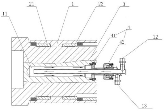
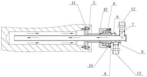
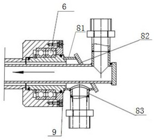
[0004] The embodiment of the present invention provides a cooling device for the tilting shaft, which solves the problems of the deformation of the tilting shaft and the jamming of the supporting copper sleeve, and realizes that after the circulating cooling water passes through the water inlet pipe, the cooling water passes through the inside of the tilting shaft, and the inside of the tilting shaft The heat is taken away, and then enters the return water system through the outlet pipe, and the internal temperature of the tilting shaft is reduced by circulating cooling

Method used


Image

  • Cooling device and cooling method for tilting shaft
  • Cooling device and cooling method for tilting shaft
  • Cooling device and cooling method for tilting shaft

Examples


Embodiment Construction

[0030] The technical solutions in the embodiments of the present invention will be clearly and completely described below with reference to the accompanying drawings in the embodiments of the present invention. Obviously, the described embodiments are part of the embodiments of the present invention, not all of the embodiments. Based on the embodiments of the present invention, all other embodiments obtained by those of ordinary skill in the art without creative efforts shall fall within the protection scope of the present invention.

[0031] In the description of the embodiments of the present invention, it should be noted that the terms "center", "upper", "lower", "left", "right", "vertical", "horizontal", "inner", "outer" The orientation or positional relationship indicated by ” etc. is based on the orientation or positional relationship shown in the accompanying drawings, and is only for the convenience of describing the embodiments of the present invention and simplifying ...


PUM


Abstract

The invention discloses a cooling device and a cooling method for a tilting shaft, and belongs to the technical field of blast furnace bell-less top equipment. The problems that the tilting shaft is made of alloy steel, is influenced by heavy load and high temperature and possibly cannot work normally or the tilting shaft deforms are solved. The cooling device comprises a box body, the tilting shaft, a water-cooled pipe support, a water inlet pipe and a water outlet pipe; the tilting shaft is installed in the box body, the tilting shaft is provided with an installation hole, the water-cooled pipe support is installed at a hole opening of the installation hole, and the water-cooled pipe support and the tilting shaft rotate relative to the box body at the same time; the water inlet pipe penetrates through the water-cooled pipe support from the outside of the tilting shaft and extends into the bottom end of the installation hole; the caliber of the water inlet pipe is smaller than that of the installation hole, and a gap is reserved between the water inlet pipe and the water-cooled pipe support; and the water outlet pipe sleeves the water inlet pipe, one end of the water outlet pipe is connected with the water-cooled pipe support, and the other end of the water outlet pipe is bent downwards along the position, close to the end part, of the water inlet pipe and is intersected and fixed with the water inlet pipe. According to the cooling device, the problems of deformation of the tilting shaft and jamming with a supporting copper sleeve are solved.

Description

technical field [0001] The present application relates to the technical field of blast furnace bellless top equipment, and in particular, to a cooling device and a cooling method for a tilting shaft. Background technique [0002] At present, there are various types of chute lifting mechanisms in blast furnace distributors at home and abroad, such as hydraulic cylinder driven lever type, single-side worm gear reducer drive, double-side worm gear reducer drive and so on. [0003] The reducer and tilting reducer used for the blast furnace top distributor are installed on the rotating chassis inside the water-cooled distributor, and the tilting shaft is installed on the distributor tilting reducer, which is used to hang the distribution chute, so that the distribution chute is tilted, and the tilting bearing is loaded. The weight of the entire distribution chute, the maximum distribution chute weight is 7.5 tons; the front end of the tilting shaft is in direct contact with the b...

Claims


Application Information

Patent Timeline
IPC IPC(8): C21B7/20C21B7/10
CPCC21B7/20C21B7/10
Inventor 杨立江王岗李栋
Owner SINOSTEEL XIAN MACHINERY
Why Eureka
Eureka Blog
Learn More