Radiator fan

A technology for cooling fans and cylinders, applied in electromechanical devices, electrical components, liquid fuel engines, etc., can solve problems such as collisions, fan rotors easily detached from fans, and instability.

Inactive Publication Date: 2009-02-04
FU ZHUN PRECISION IND SHENZHEN +1
View PDF0 Cites 11 Cited by
  • Summary
  • Abstract
  • Description
  • Claims
  • Application Information

AI Technical Summary

Problems solved by technology

When the cooling fan is working, the rotor rotates at a high speed relative to the stator. When the fan blades rotate, airflow is generated, and the airflow produces an outward pulling force on the fan blades and the rotor. Especially when the fan is in an inverted state, the rotor itself Under the action of gravity, the fan rotor is easy to separate from the fan outwards, resulting in axial oscillation and instability when the rotor rotates, and the axial oscillation of the shaft often leads to continuous collisions between the shaft and the center column, resulting in running increase in noise

Method used


Image

  • Radiator fan
  • Radiator fan
  • Radiator fan

Examples


Embodiment Construction

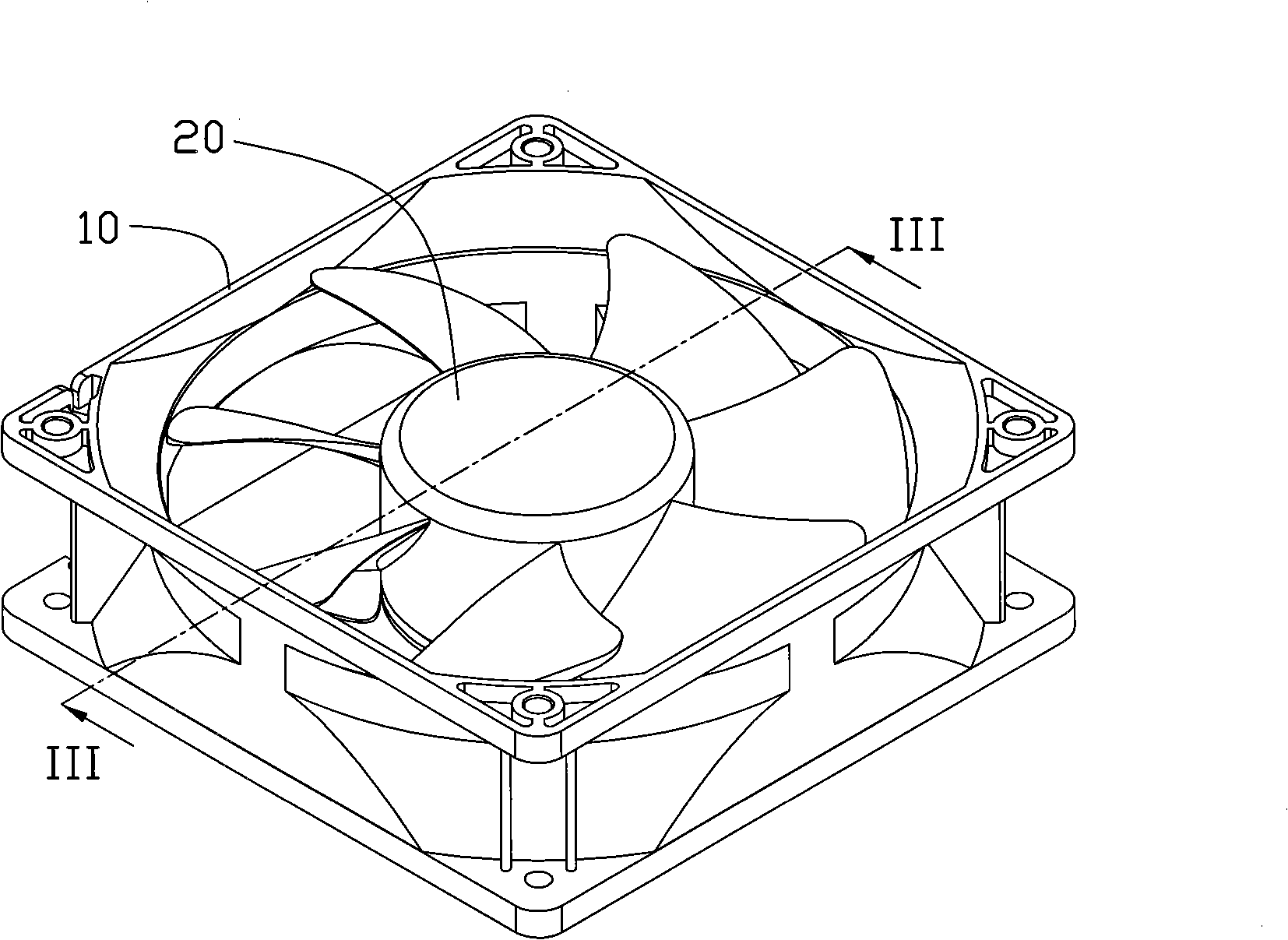
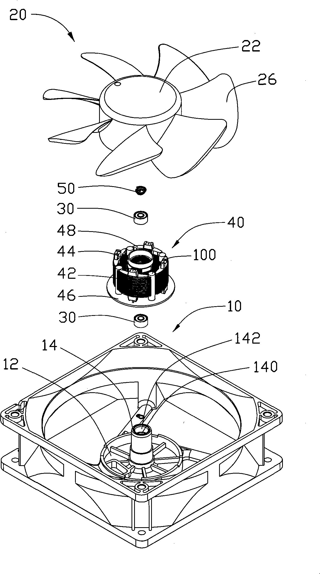
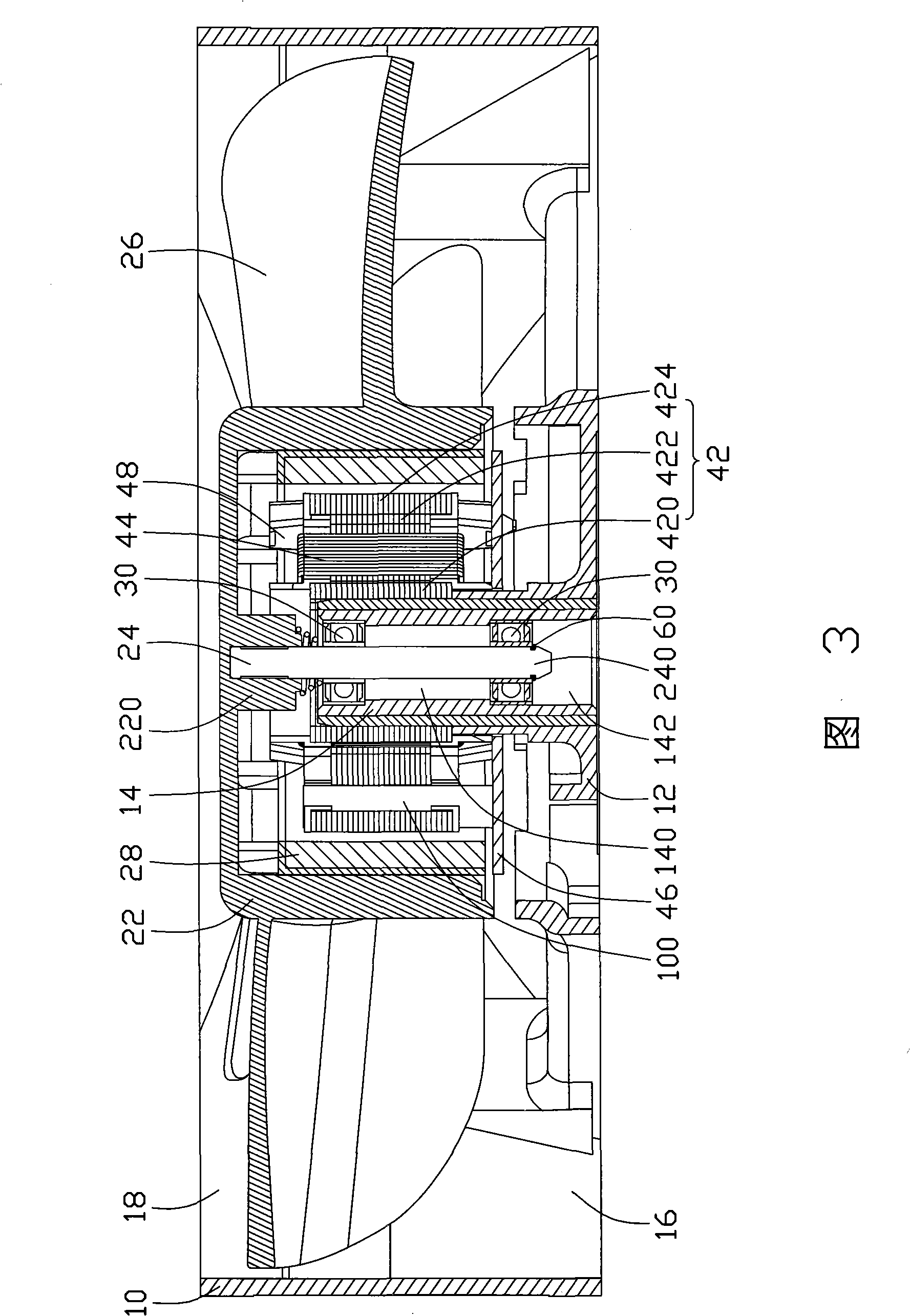
[0012] see figure 1 Referring to FIG. 3 , the cooling fan includes a fan frame 10 , a pair of bearings 30 , a rotor 20 and a stator 40 .

[0013] The fan frame 10 is square, and a through hole for accommodating the stator 40 and the rotor 20 is formed in the center, and an air inlet 18 and an air outlet 16 are respectively formed in the through hole corresponding to two sides (upper side and lower side) of the fan. The fan forms a pedestal 12 at the central position of the air outlet 16. The center of the pedestal 12 protrudes upwards to form a central column 14. A perforation 140 is formed in the center of the central column 14. The upper and lower ends of the central column 14 respectively form a The opening 142 is larger in diameter than the perforation 140 thereof.

[0014] The outer diameter of the pair of bearings 30 is substantially equivalent to the diameter of the opening 142 of the center column 14 , and are respectively accommodated in the openings 142 at the upper...


PUM


Abstract

A heat radiating fan includes a fan frame the center of which is formed with a middle column; at least one bearing is arranged in the middle column; a stator is sheathed in the periphery of the middle column; a rotor can rotate relatively to the stator; the rotor includes a hub annularly arranged on the periphery of the stator, a plurality of fan vanes annularly arranged on the periphery of the hub, a permanent magnet ring closely arranged on the inner side of the hub as well as a rotating shaft vertically extending from the center of the hub and being accepted in the bearing; the stator includes the iron core of the stator, a coil twisted on the iron core of the stator as well as a circuit board electrically connected with the coil; the iron core of the stator includes an annular part and a plurality of claw poles extending from the periphery of the annular part to the external radical direction; at least one column body is upwards and convexly arranged on the circuit board; the column is correspondingly arranged between two neighboring claw poles; the material of the column is a permeablility magnetic material and has a magnetic attraction with the permanent magnet ring of the rotor, thereby attracting the rotor and maintaining the balancing rotation of the rotor.

Description

technical field [0001] The invention relates to a heat dissipation fan, in particular to a heat dissipation fan capable of maintaining a balanced rotation of a rotor. Background technique [0002] As heat-generating electronic components such as central processing units run faster and faster, they generate more and more heat. To ensure the normal operation of these electronic components, they must be dissipated quickly and efficiently. Usually, the industry installs a heat sink on the heat-generating electronic components such as the central processing unit to assist its heat dissipation. More effective heat dissipation. [0003] Existing cooling fans generally include a stator and a rotor that is arranged around the periphery of the stator and can rotate relative to the stator. The stator has several coils for generating an alternating magnetic field after electrification, and the rotor includes a hub and a permanent magnet disposed inside the hub and facing the stator c...

Claims


Application Information

Patent Timeline
Patent Type & Authority Applications(China)
IPC IPC(8): F04D25/08F04D29/66H02K7/14H02K1/14F04D29/056
CPCF04D25/0646F04D29/051F04D29/058F04D25/062
Inventor 颜剑锋张永康黄英敏孙泓
Owner FU ZHUN PRECISION IND SHENZHEN
Why Eureka
Try Eureka