Shuttle valve

A shuttle valve and check valve technology, applied in the field of valves, can solve problems such as time-consuming, mistakes by caregivers, and inconvenience for caregivers

Inactive Publication Date: 2009-02-04
SMITHS MEDICAL ASD INC
View PDF0 Cites 18 Cited by
  • Summary
  • Abstract
  • Description
  • Claims
  • Application Information

AI Technical Summary

Problems solved by technology

This process is inconvenient and time consuming for the caregiver if the valve and syringe are not adjacent to each other
[0003] There is also a risk of caregiver error and the possibility of inadvertently fluidly connecting a fluid source to a valve port connected to a patient due to valve misuse

Method used


Image

  • Shuttle valve
  • Shuttle valve
  • Shuttle valve

Examples


Embodiment Construction

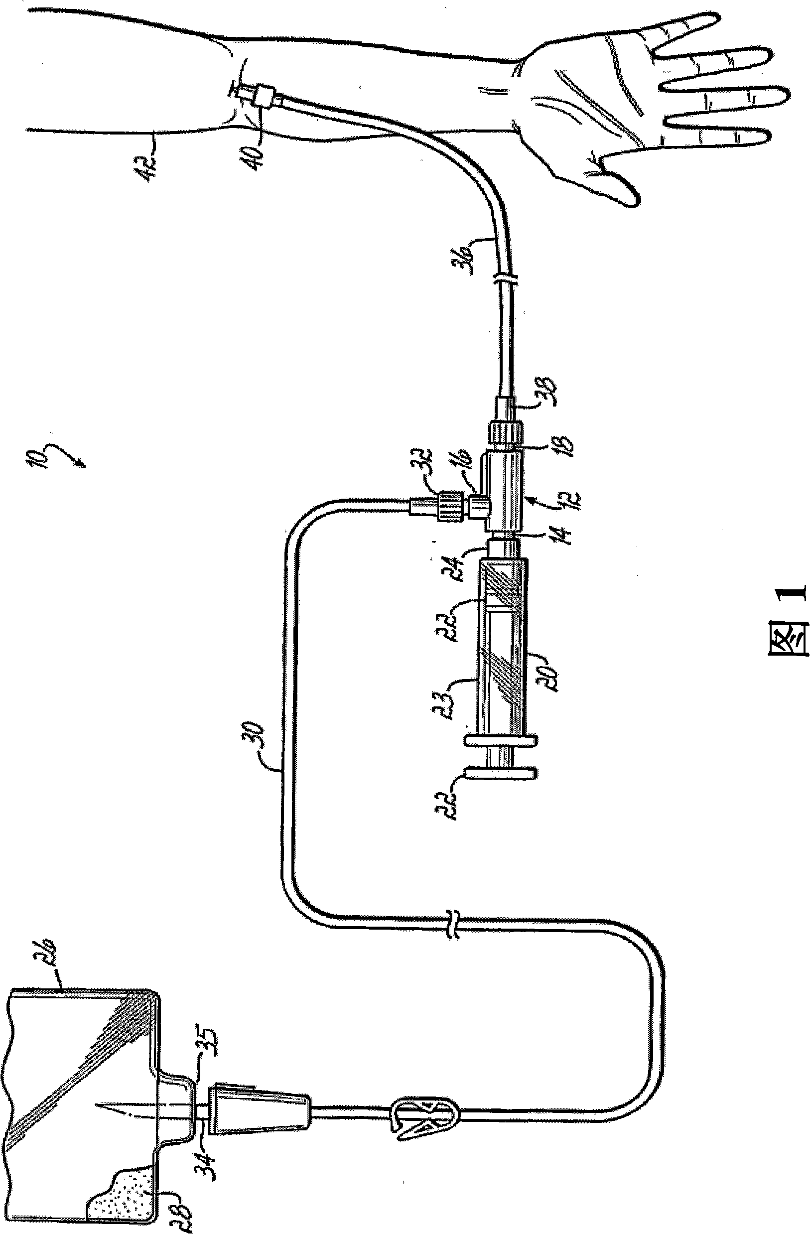
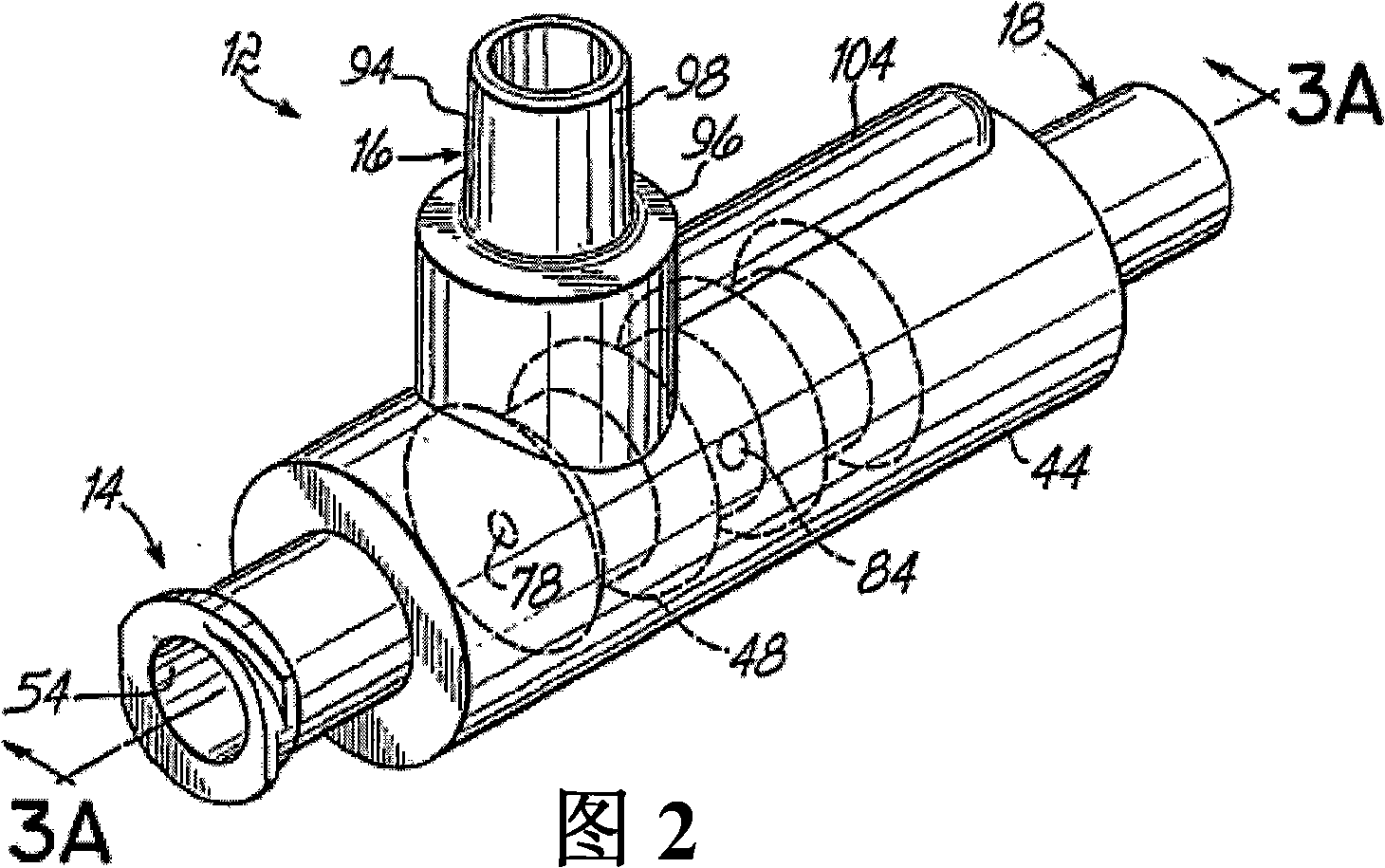
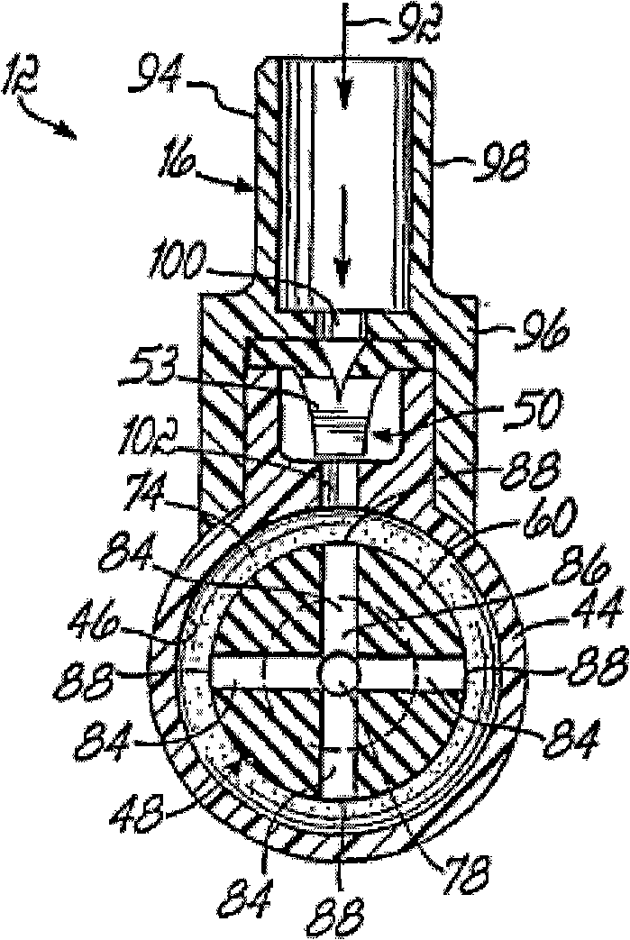
[0022] Referring to the drawings, FIG. 1 illustrates a system 10 for intravenously dispensing medical fluids to a patient, the system 10 including a shuttle valve 12 according to a first embodiment of the present invention. Shuttle valve 12 includes a common port 14 , an inlet port 16 and an outlet port 18 . The liquid dispensing system 10 further includes a syringe 20 connected to the common port 14 . The syringe 20 comprises a piston 22 movable within a barrel 23 which is integral at the outlet end with a ring 24 connected to the common port 14, as will be described in further detail below.

[0023] System 10 further includes a source of fluid to be dispensed, which includes a bag 26 (commonly referred to as an intravenous bag (IV bag)) containing fluid 28 . Fluid 28 may include various medicines and various liquids, such as saline. System 10 further includes a first length of tubing 30 (which may be a single tubing or a plurality of interconnected tubing). A tube 30 is c...


PUM


Abstract

A shuttle valve (12, 150, 230) is provided having a body (44, 152, 232) defining an interior chamber (46, 154, 234). The valve (12, 150, 230) includes inlet (16, 158, 238), outlet (18, 160, 240) and common (14, 156, 236) ports that are coupled to the body (44, 152, 232). A shuttle (48, 162, 242) is translatably disposed within the chamber (46, 154, 234) between a first position wherein the inlet (16, 158, 238) and common (14 ,156, 36) ports are fluidicly coupled and the common (14, 156, 236) and outlet (18, 160, 240) ports are fluidicly uncoupled, and a second position wherein the outlet (18, 160, 240) and common (14, 156, 236) ports are fluidicly coupled and the common (14, 156, 236) and inlet (16, 158, 238) ports are fluidicly uncoupled. A first check valve (50) coupled to the inlet port (16, 158, 238) to permit fluid flow through the inlet port (16,158,238) into the chamber (46, 154, 234) and to prevent fluid from discharging therethrough. A second check valve (50) is coupled to the outlet port (18, 160, 240) in a manner to permit fluid to discharge from the chamber (46, 154, 234) through the outlet port (18, 160, 240) and to prevent fluid from flowing through the outlet port (18, 160, 240) into the chamber (46, 154, 234).

Description

Technical field: [0001] The present invention relates to valves, and more particularly to shuttle valves that may be used in systems for intravenously delivering medical fluids to patients. Background technique: [0002] Various systems are known in the medical field for delivering different fluids, such as saline and medicines to patients intravenously. One known system includes a three-way stopcock and a syringe that are manually operated by a caregiver. One inlet port of the valve is in fluid communication to a liquid source, while a common port is connected to a syringe and an outlet port is in fluid communication to a patient. Although this general system has been successfully applied, it still has some disadvantages. First, when a caregiver enters the patient room to administer intravenous fluids, the caregiver must first check the stopcock to ensure that the valve position is fluidly connected to the inlet port and the common port, which in turn fluidly connects the...

Claims


Application Information

Patent Timeline
Patent Type & Authority Applications(China)
IPC IPC(8): A61M5/142
CPCA61M39/24F16K11/0712A61M2039/2493A61M2039/2473Y10T137/2544A61M39/223A61M2039/2486Y10T137/7838F16K11/0716A61M5/14216F16K15/147F16K31/1226
Inventor 约瑟夫·M·艾姆雷丹尼·F·林肯
Owner SMITHS MEDICAL ASD INC
Why Eureka
Try Eureka