
Underwater equipment recovery

A technology of underwater equipment and equipment, applied in the direction of ships, ship salvage, transportation and packaging, can solve complex problems and achieve the effect of effective coverage

Inactive Publication Date: 2011-08-03
OHM
View PDF6 Cites 0 Cited by
  • Summary
  • Abstract
  • Description
  • Claims
  • Application Information

AI Technical Summary

Problems solved by technology

However, this solution is too complex and requires prior knowledge of the object's position

Method used


Image

  • Underwater equipment recovery
  • Underwater equipment recovery
  • Underwater equipment recovery

Examples


Embodiment Construction

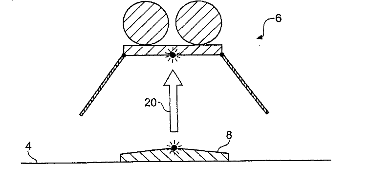
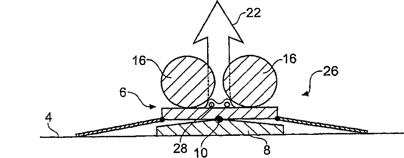
[0045] figure 2 , 3 The apparatuses 22, 24 for recovering equipment deployed underwater according to an embodiment of the present invention are schematically shown. In this example, the equipment is an equipment module that is arranged on the seabed 4 and constitutes the electromagnetic receiver 26. The receiver is similar to and can be understood from the electromagnetic receiver 2 shown in FIG. 1. In other words, the receiver 26 includes a conventional recycling mechanism, as described above, the recycling mechanism includes a floating device 16, a counterweight 8 and a releasable connector 10. Therefore, the devices 22, 24 are used to recover the receiver when the conventional recovery mechanism fails. It can be understood that in other examples, the receiver (or other equipment) may not include a traditional recycling mechanism, and the devices 22 and 24 will become the main means for recycling the equipment. In both cases, the principle underlying the recovery step is th...


PUM


Abstract

Disclosed is an apparatus and a method for recovering equipment from within a body of water. The apparatus comprises a frame supporting a mesh and an engagement element. The engagement element is shaped to co-engage with the mesh and is attached to the equipment to be recovered prior to its deployment. Following deployment of the equipment, its recovery can be affected by lowering the mesh supported by the frame onto the equipment to cause the engagement element and the mesh to co-engage. The frame and mesh are then lifted to the surface of the water bringing the equipment with them. Recoverymay include searching for the equipment by monitoring a load associated with the frame and the mesh as it is lowered and raised at different locations, whereby an appropriate increase in load is taken to indicate that the equipment has become attached to the mesh.

Description

Technical field [0001] The invention relates to the recovery of underwater equipment, such as equipment that has been deployed on the seabed during a survey. Background technique [0002] For various reasons, the equipment can be set up (or tethered) on the seabed, or towed at a certain depth. For example, during underwater construction for petroleum and mineral exploration, geological prospecting, meteorological and marine monitoring, and for assisting vessel navigation, equipment is usually deployed underwater. The standard method for recycling such devices relies on acoustically triggered release mechanisms. [0003] Fig. 1A schematically shows a known electromagnetic receiver 2 which is deployed on the seabed 4 during an electromagnetic survey and is recovered using existing technology (GB2382875 [1]) at the end of the survey. A similar system is also described in US5770945 [2]. The receiver 2 has a main body 6 including an antenna 12, an instrument housing 14 and a floating...

Claims


Application Information

Patent Timeline
Patent Type & Authority Patents(China)
IPC IPC(8): B63C7/02B63C7/16B63C7/18
CPCB63C7/16B63C7/18B63B2241/02
Inventor J·H·尼科尔斯
Owner OHM
Learn More