
Load-reducing device for rolling bearing type thrust bearing for hydraulic turbine

A technology of rolling bearing and load reducing device, applied in the directions of hydroelectric power generation, engine components, machines/engines, etc., can solve the problems of high pressure oil cleanliness and tightness requirements, complicated installation and debugging, burning thrust pads, etc., to reduce wear and tear , easy to debug, to prevent the effect of burning tiles

Inactive Publication Date: 2009-02-11
TSINGHUA UNIV
View PDF0 Cites 3 Cited by
  • Summary
  • Abstract
  • Description
  • Claims
  • Application Information

AI Technical Summary

Problems solved by technology

However, the installation and debugging of this high-pressure oil jacking device is complicated, and the requirements for the cleanliness of the high-pressure oil and the sealing of the device are very high, and it is easy to fail and burn the thrust pad.

Method used


Image

  • Load-reducing device for rolling bearing type thrust bearing for hydraulic turbine
  • Load-reducing device for rolling bearing type thrust bearing for hydraulic turbine
  • Load-reducing device for rolling bearing type thrust bearing for hydraulic turbine

Examples


Embodiment Construction

[0015] The present invention will be further described below in conjunction with the accompanying drawings and specific embodiments, but not as a limitation of the present invention.

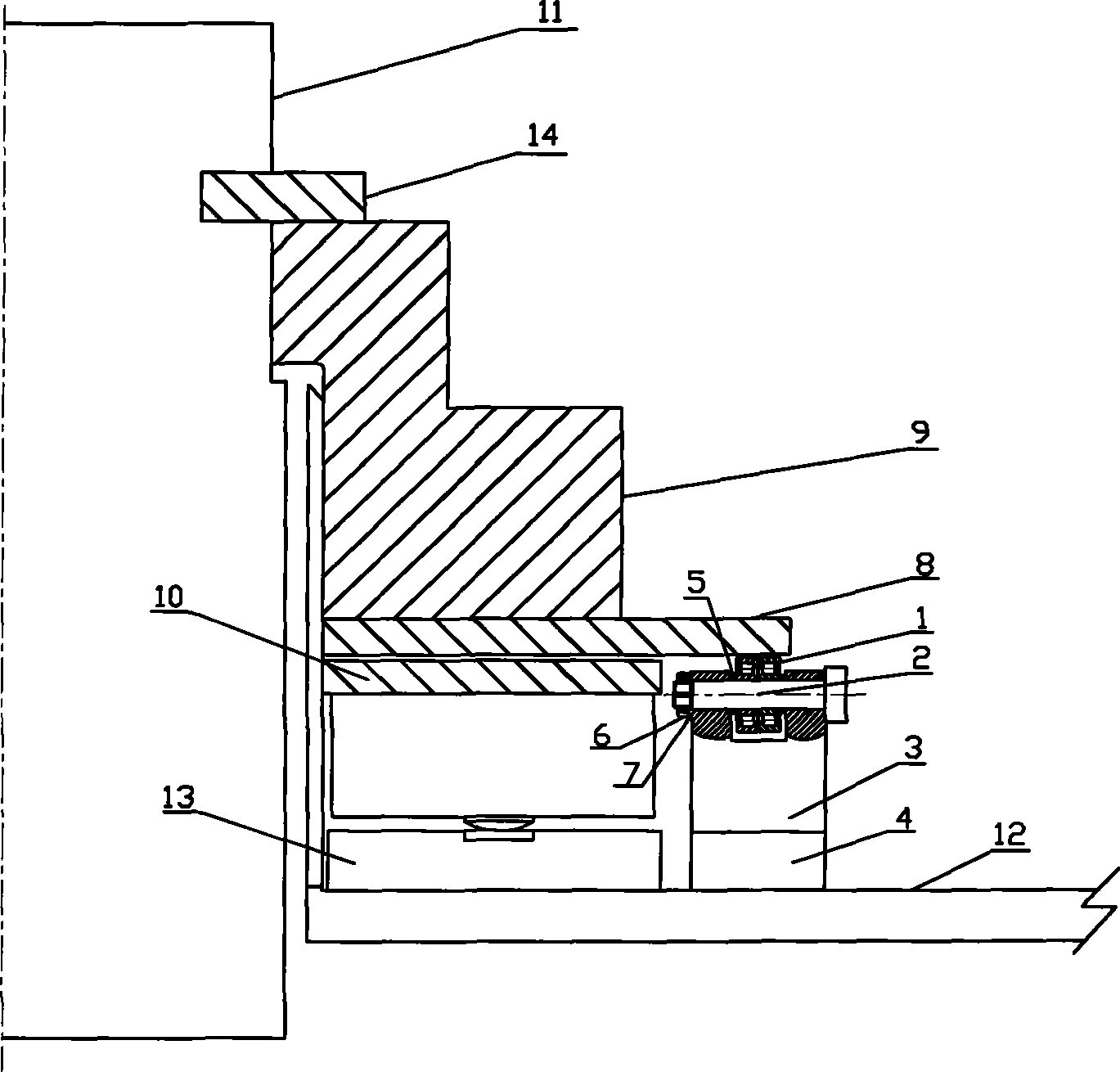
[0016] see figure 1 , the main shaft 11 is provided with a snap ring 14, and the bottom of the snap ring 14 is provided with a thrust head 9, a mirror plate 8, a thrust tile 10 and a thrust tile seat in sequence, and the thrust bearing load reduction device of the rolling bearing type hydraulic turbine is installed on the frame 12, located on The outer side of the thrust tile 10 of the water turbine, and the lower side of the mirror plate 8.

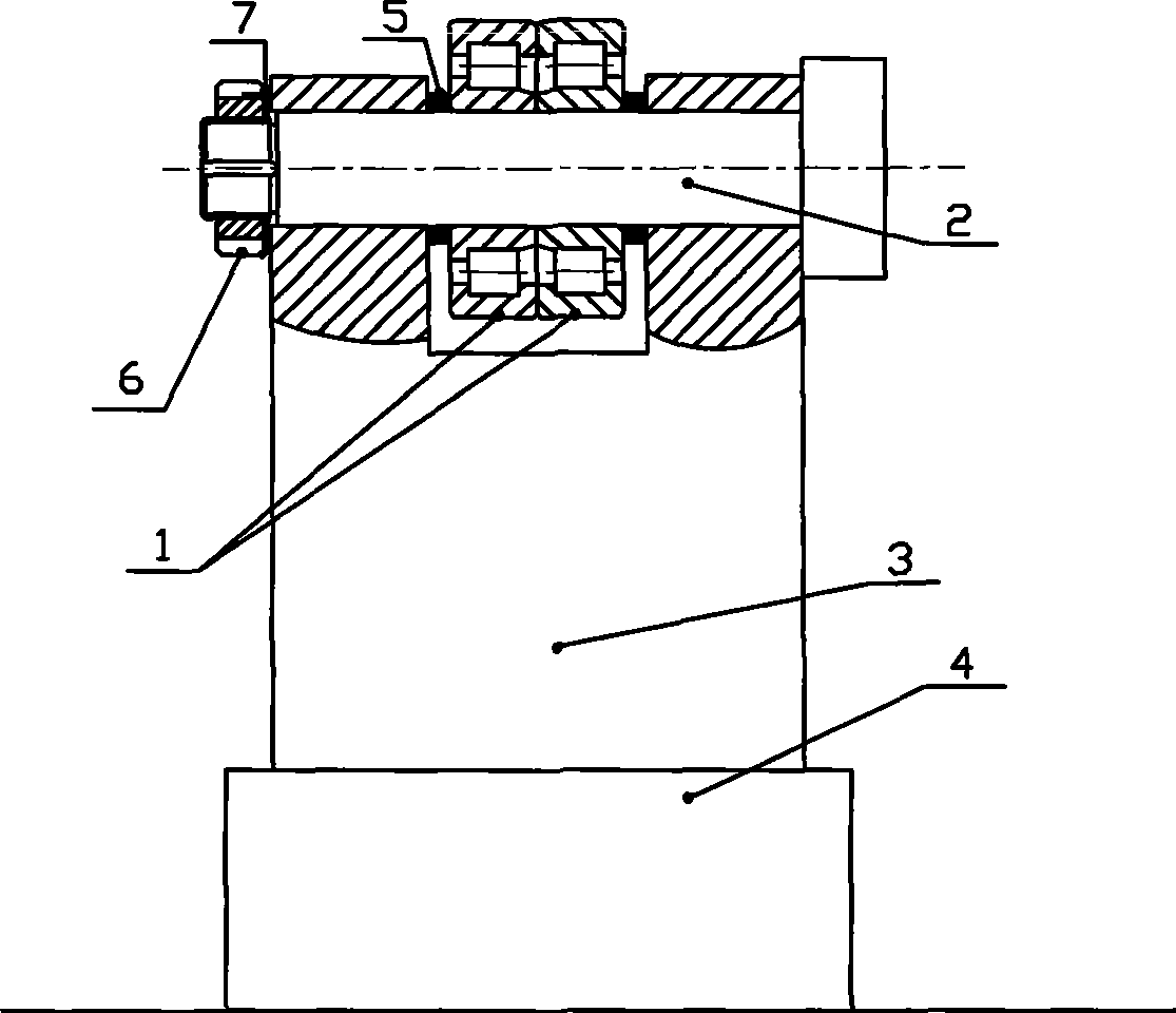
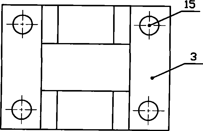
[0017] see figure 2 and figure 1 , a rolling bearing type hydraulic turbine thrust bearing load reduction device, including a support 3, a fixed shaft 2 is installed on the top of the support 3 through a round nut 6 and a stop washer 7, and a rolling bearing 1 is installed on the fixed shaft 2 through a sleeve 5, A height adjustment device 4 is provide...


PUM


Abstract

The invention discloses a thrust bearing load-reduce device of a rolling bearing type water turbine; the device comprises a supporting member, the upper face of the supporting member is provided with a fixed shaft which is equipped with a rolling bearing, the lower face of the supporting member is provided with a height adjuster which comprises an upper connecting piece connected with the supporting member, a lower connecting piece is correspondingly arranged below the upper connecting piece, the contact face of the upper connecting piece and the lower connecting piece is an inclined surface, the two ends of the lower connecting piece are provided with bolts which can cause the lower connecting piece to do left-right movement; the inner ring of the rolling bearing is fixed on a supporting shaft, the outer ring thereof can rotate freely and is in direct contact with a runner plate for bearing load; the adoption of the device can greatly reduce the pressure born by a thrust bearing pad when the water turbine is started or stopped, reduces the abrasion of the thrust bearing pad, and prevents the accidents such as pad burning, and the like, caused by the faults of a high pressure oil load-reduce device. The device has the advantages of simple structure, convenient debugging, reliable running, low cost, etc.

Description

technical field [0001] The invention relates to a mechanical load reduction device in mechanical engineering, in particular to a rolling bearing type water turbine thrust bearing load reduction device, which is used to reduce the load on the thrust pad. Background technique [0002] In large-scale hydroelectric generating units, the thrust bearing load is relatively large. During the start-up and shutdown of the unit, due to the low speed, the oil film of the thrust pad is relatively thin, and the friction coefficient is relatively large. There is a danger of semi-dry friction between the thrust pad and the mirror plate. state, which is very unfavorable to the lubrication of thrust bearings. In order to solve the problem of difficulty in establishing an oil film in a thrust bearing with a large load, the main method at present is to use a high-pressure oil jacking device to raise the mirror plate during the start-up and shutdown of the unit, so that the oil film is formed on...

Claims


Application Information

Patent Timeline
IPC IPC(8): F03B11/06
CPCY02E10/226Y02E10/20
Inventor 高志刘向锋刘莹褚福磊梅贵
Owner TSINGHUA UNIV
Learn More