Mechanical self-adapting deformation blade

An adaptive and mechanical technology, applied in the field of wind turbine blades, can solve the problems of easy swelling of blades, extra energy consumed by blades, energy consumption, etc., achieve low sealing requirements, improve wind energy utilization, and simple manufacturing process Effect

Active Publication Date: 2016-08-17
UNIV OF SHANGHAI FOR SCI & TECH
View PDF4 Cites 0 Cited by
  • Summary
  • Abstract
  • Description
  • Claims
  • Application Information

AI Technical Summary

Problems solved by technology

Among them, for the method of using inflatable self-adaptive deformation blades, the blades are easy to swell after inflation, resulting in difficulty in deformation, and the air leakage of the material will cause the wind turbine to fail to operate normally; for wind turbines that use electric drive to actively deform the blades, relying on External energy provides power, and there is a certain delay in adapting to the wind direction, and the deformation of the blade consumes additional energy; for some other methods, the aerodynamic performance of the wind turbine is changed by adding original parts to the blade after the blade design is completed.
[0005] Among the existing deformed blades, most of them adopt the electric drive method to deform the blades. In addition to supporting the corresponding driver program, it also needs to consume additional energy to drive the deformation.
In addition, due to the fast rotation speed of the wind turbine, there is still a certain hysteresis phenomenon caused by the surface deformation of the blade driven by the driver, which is not conducive to improving the wind energy utilization rate of the wind turbine.

Method used


Image

  • Mechanical self-adapting deformation blade
  • Mechanical self-adapting deformation blade
  • Mechanical self-adapting deformation blade

Examples


Embodiment Construction

[0023] The present invention will be further described below in conjunction with the accompanying drawings and embodiments.

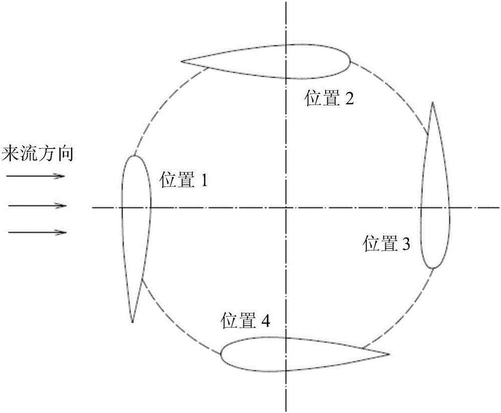
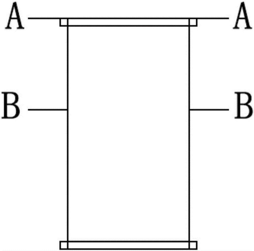
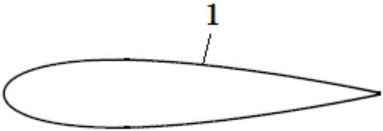
[0024] like Figure 1 to Figure 8 As shown, the main body of the mechanical self-adaptive deformable blade of the present invention includes a flexible airfoil shell 2, a crescent-shaped cylinder 3, a beam 4, a flexible skin 1, and the like.

[0025] like Figure 2 to Figure 4 As shown, the flexible airfoil shell 2 is sealed by the upper and lower ends of the blades with an elastic flexible skin 1, and the flexible skin 1 deforms with the deformation of the blades. The flexible airfoil shell 2 can be made into a NACA airfoil shape with a certain thickness. NACA airfoil sides are integral and have no seams. The leading edge and the trailing edge of the flexible airfoil shell 2 are connected by a crossbeam 4, and the crescent-shaped column is installed on the crossbeam through a hinge, and the crescent-shaped column can be flexibly moved. There is a g...


PUM


Abstract

The invention relates to a mechanical self-adapting deformation blade. The mechanical self-adapting deformation blade consists of a flexible wing type shell, a crescent cylinder and a cross beam, wherein the crescent cylinder is mounted on the cross beam in a hinged mode; a hinge can move flexibly; the flexible wing type shell is sealed by an elastic flexible skin from the upper and lower ends of the blade; the flexible skin deforms along with deformation of the blade; the flexible wing type shell is in the shape of an NACA wing with a certain thickness; and a front edge and a tail edge of the flexible wing type shell are connected by the cross beam. The mechanical self-adapting deformation blade does not need to consume electric energy additionally, and does not need matched deformation driving equipment or procedures. Under the effect of wind power, the shape of the blade can be changed, so that use ratio of wind energy is improved. The shell is designed mechanically, requirements to airtightness are low, and a manufacturing technology is simple.

Description

technical field [0001] The invention relates to a wind turbine blade, in particular to a mechanical adaptive deformable blade. Background technique [0002] Wind turbines are usually divided into horizontal axis wind turbines and vertical axis wind turbines according to the structure of the wind rotor and its position in the airflow. Compared with the horizontal axis wind turbine, the vertical axis wind turbine has the advantages of no need to face the wind, low noise, flexibility and convenience, safety and reliability, beautiful appearance and simple maintenance. It is a very good form of wind energy utilization and has broad application prospects. . [0003] The design of wind turbine blades directly affects the conversion efficiency of wind energy and its annual power generation, which is an important part of wind energy utilization. In order to comprehensively balance the aerodynamic performance at different phases, the blades of today's Darrieus lift wind turbines mo...

Claims


Application Information

Patent Timeline
IPC IPC(8): F03D3/06
CPCF03D3/062Y02E10/74Y02P70/50
Inventor 王莹王昆朋李冬磊谢海军褚舒颖向佳佳余欣励顾嘉淳
Owner UNIV OF SHANGHAI FOR SCI & TECH
Why Eureka
Try Eureka