
Vertical shaft giant energy and energy-collecting wind-driven generator group

A technology for wind turbines and wind turbines, which is applied to wind turbine combinations, wind turbines, and wind turbines at right angles to the wind direction, etc., can solve the problems of difficult mountaintop construction and application requirements, difficult effective application, and difficult giant energy design, etc. Achieve the design level of single-machine output capacity and facilitate installation, management and maintenance.

Inactive Publication Date: 2009-02-11
陈晓通
View PDF0 Cites 3 Cited by
  • Summary
  • Abstract
  • Description
  • Claims
  • Application Information

AI Technical Summary

Problems solved by technology

However, the existing vertical-axis wind turbines and their wind turbines are difficult to achieve huge energy design, so it is difficult to form a huge benefit application, and it is difficult to meet the application requirements of mountaintop construction
[0007] The main reason why the existing vertical axis wind turbine wind turbines are difficult to achieve the design of huge output capacity is that the rotating wind panels that rotate around the vertical axis do not have a definite design for the direction of the wind force, and they all use spoon-shaped and ∧-shaped panels similar to those used by meteorological stations for wind measurement. The structure of coordinating rotation in the downwind and upwind directions makes the output force of the windward side greater than that of the upwind side, thus forming a full-wind rotation regardless of the windward direction, but the upwind side also has greater wind resistance, so its The condition that the rotation can be realized is only because there is no load or the load is very small. It can be used in areas with small power generation requirements such as electric lighting.
[0008] There is also a design that arranges the blades on the rotating wind plate around the vertical axis, forming a closed state against the wind when it is facing the wind, and is naturally blown up when it reaches the downwind side, but its shape is bulky, and it is difficult to blow it up and turn when the wind is not strong. Blades on one side, less active control, making it difficult to use effectively
There is also a design in which the blades are closed and opened on the rotating wind plate driven by the mechanical rotating device installed inside the vertical shaft, but it can only realize a symmetrical design formed by two rotating wind plates, and it is difficult to form a simultaneous three- 8 rotating wind panels are driven at the same time, and the common design of 4-8 rotating wind panels is a necessary condition for efficient and sufficient wind collection to realize the design of huge energy output

Method used


Image

  • Vertical shaft giant energy and energy-collecting wind-driven generator group
  • Vertical shaft giant energy and energy-collecting wind-driven generator group
  • Vertical shaft giant energy and energy-collecting wind-driven generator group

Examples


Embodiment Construction

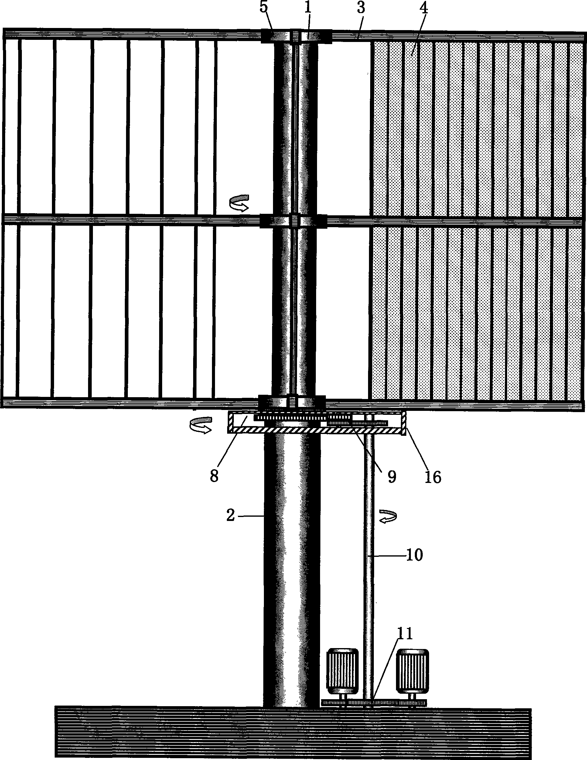
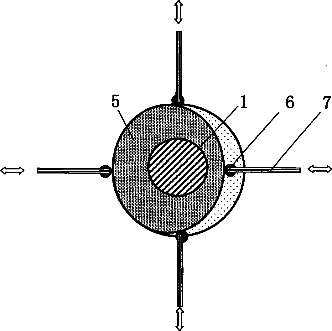
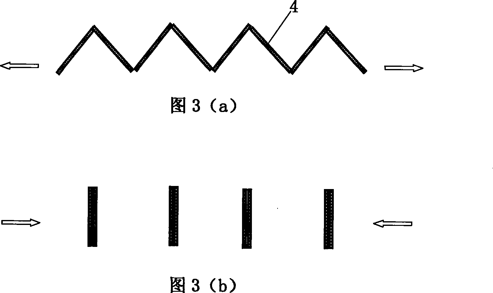
[0023] combine figure 1 , 2 , 5) It can be seen that when the vertical axis giant energy wind turbine is working against the wind, it first needs to measure the direction of the wind force, and then determine and adjust the direction of the concave portion of the wind-facing guide rail disk 5 according to the direction of the wind force, so that it can be used when the operating position of each rotating wind force plate 3 arrives. The windward inverter plate 4 on it is closed due to the cooperative drive of the rolling wheel 6 and the push-pull rod 7, and the direction of the convex part of the windward guide rail plate 5 can make the operating position of the rotating wind plate 3 unfold after it is in place. The push-pull spring realizes reset, and when it is close to the downwind windward angle, the windward inverter board gradually expands, and gradually shrinks after reaching the vertical wind direction.

[0024]Through the above process, the rotating wind panel is driv...


PUM


Abstract

The invention relates to a vertical shaft giant energy wind power generator group, which comprises the main structure of a vertical shaft, a rotational wind power plate, an upwind inverting plate, a yawing guide disc form, and the like, and can realize the giant output capacity design and cascade output capacity and regulation of the vertical shaft generator; a plurality of vertical shaft giant energy wind power generators are arrayed in series to realize unite power output and the unite power output is combined with a multi-generator system to form a vertical shaft giant energy and energy collecting wind power generator group; the wind power generator group brings in the operation mode of the vertical wind power turbine into the determination and regulation control structure of the wind power direction for the first time; the wind power generator group can lead a rotational wind power plate to realize fully-closed wind collection and super low resistance rotary operation, thus forming an unprecedented giant output capacity design; the wind power generator group as well can use remote control to realize the full opening operation of the upwind inverting plate on the rotational wind power plate, thus realizing the advantageous effects of resistance to impact of typhoon; the equipment structure of the wind power generator group is simple and convenient for decentralized transport at top of hills; the wind power generator group has giant wind collecting surface, particularly being suitable for the construction at top of hills, meanwhile being suitable for the construction of wind turbines on sea islands and on sea.

Description

technical field [0001] The invention relates to a novel vertical-axis wind-driven generator set, in particular to a vertical-axis wind-driven generator set and a combined energy-gathering set that adopts a wind-facing guide rail disk control structure to realize an unprecedented design of huge energy output capability. Background technique [0002] The key to the development of wind power is the development of wind power equipment, and the key to the development of wind power equipment is the development of equipment types. Through the diversified development and design of wind power equipment, it can break through the technical bottlenecks, capacity limits, and foreign patent barriers formed by the long-term accumulation of existing types of wind turbines, and can subvert the wind energy reserves, development space, and development based on existing types of wind power equipment. The basis of most existing complete sets of theories such as wind collection method, benefit ev...

Claims


Application Information

Patent Timeline
Patent Type & Authority Applications(China)
IPC IPC(8): F03D9/00F03D7/06F03D3/02F03D9/25F03D15/00
CPCY02E10/74
Inventor 陈晓通
Owner 陈晓通
Learn More