
Pin joint structure for universal joint

A universal joint and pivot joint technology, which is applied in the field of universal joint pivot joint structure, can solve the problems of loss of working angle, large centrifugal force, and low service life, and achieve the effect of stable pivot joint structure

Inactive Publication Date: 2009-02-11
胡厚飞
View PDF0 Cites 4 Cited by
  • Summary
  • Abstract
  • Description
  • Claims
  • Application Information

AI Technical Summary

Problems solved by technology

[0005] However, the second type of universal joint 80 still has defects. The biggest defect is that the second type of universal joint 80 will easily cause the second pin 84 to separate from the connecting block 81 when it is used for a long time through power tools. Thus causing the problem that the sleeve joint 85 is separated from the connection block 81
Because when the power tool runs at a high speed, considerable centrifugal force will be generated, and the second pin 84 does not have any fixed structure, so it is easy for the second pin 84 to escape from the lack of the connecting block 81
[0006] If the second pin 84 is tightly fitted in the connecting block 81, the pivot joint structure of the second universal joint 80 cannot be removed, and once the parts are damaged, the entire set must be discarded, resulting in a rather low overall service life.
[0007] In addition, the allowable working angle range of the second type of universal joint 80 is smaller than that of the first type of universal joint 90 during operation. In this way, although the second type of universal joint 80 overcomes the vibration during operation However, it also loses the effective working angle, which affects the working ability of the universal joint 80, which is quite difficult to use and not practical.

Method used


Image

  • Pin joint structure for universal joint
  • Pin joint structure for universal joint
  • Pin joint structure for universal joint

Examples


Embodiment Construction

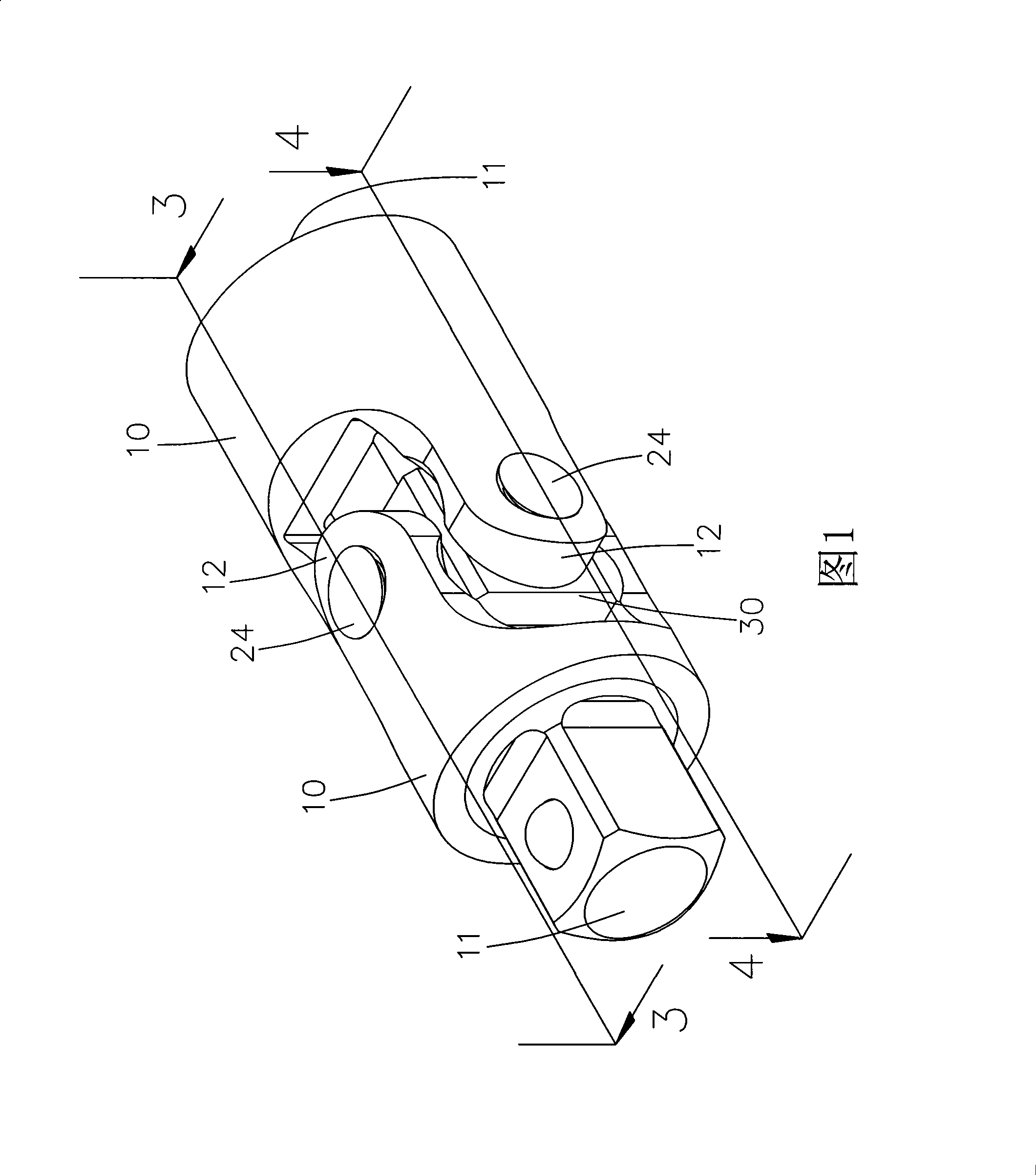
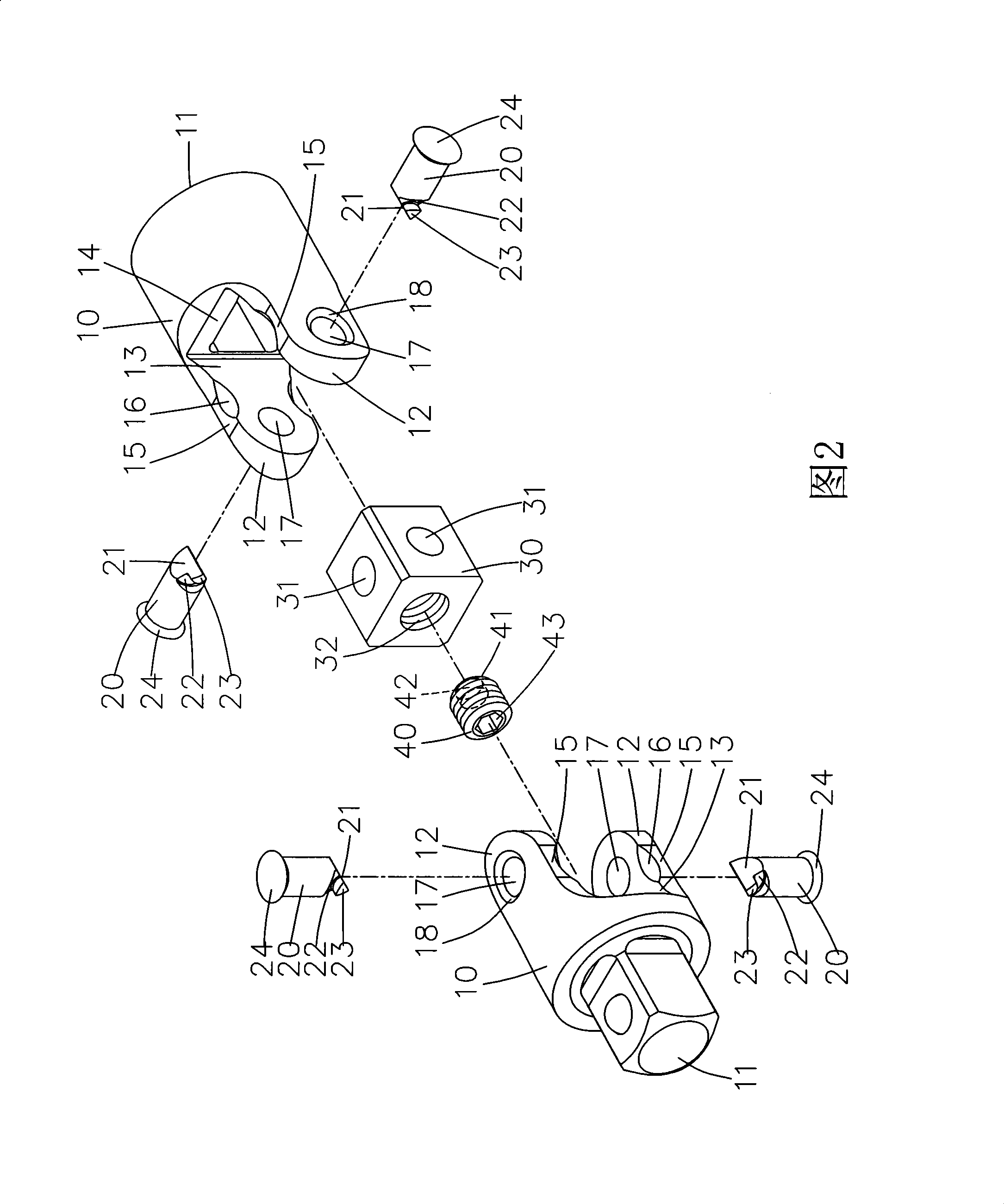
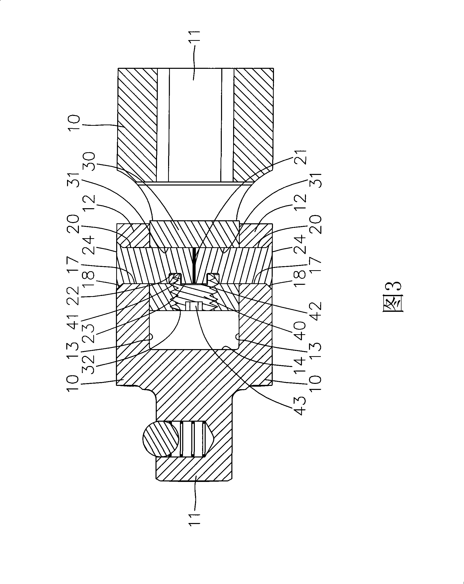
[0025] Referring to FIG. 1 and FIG. 2 , the universal joint of the present invention includes two driving parts 10 , a connecting part 30 pivotally connected between the two driving parts 10 , and a limiting part 40 disposed on the connecting part 30 . A shaft 20 is pivoted between the connecting piece 30 and the two driving pieces 10, and the limiting piece 40 is fastened to the shaft 20, so that the shaft 20 can be firmly connected to the connecting piece 30. Inside, at the same time achieve the effect of detachable.

[0026] One end of the driving element 10 is provided with a coupling end 11 for connecting the driving object or the driven object. The end of the driving member 10 opposite to the connecting end 11 is provided with a pivoting end 12 . Wherein, the coupling end 11 of the driving member 10 can be configured as a sleeve shape or a square head shape, and this change can be easily accomplished by those skilled in the art.

[0027] The pivoting ends 12 of the dri...


PUM


Abstract

The invention relates to a pivot joint structure of a universal joint, comprising two driving parts, a connecting piece and a stopper; the driving part is provided with a pivot joint end which is equipped with a pivot hole; the connecting piece is provided with two axle holes which are positioned on the same plane and cross vertically, an axial member is respectively pivotally arranged between two axle holes of the connecting piece and the pivot holes of the two driving parts, thus forming opposite pivot swinging relation between the connecting piece and the driving parts, the front part of the connecting piece is further provided with a locating hole which is communicated with the two axle holes; the stopper is installed in the locating hole of the connecting piece and is combined with the axial member to fix the axial member in the axle hole of the connecting piece, thus achieving the clamping and combining effect of quick combination and stable structure; furthermore, with the stopper which can be quickly assembled and disassembled, the assembly labor hour can be saved, thus achieving the effect of reducing assembly cost.

Description

technical field [0001] The invention relates to a universal joint, in particular to a universal joint pivot structure with a more stable pivot structure and a detachable pivot structure. Background technique [0002] Please refer to Figure 6 and Figure 7 , is the first conventional universal joint 90 structure, its connecting block 91 is set as a rectangular block, one end of the connecting block 91 is provided with a first pin 92 to pivotally connect a driving head 93, the connecting block 91 is opposite to the driving head 93 A second pin 94 is provided at one end to pivotally connect a socket joint 95 . The axis centers of the first pin 92 and the second pin 94 are perpendicular to each other but do not intersect each other, so that when the driving head 93 and the sleeve joint 95 are manually rotated, the allowable working angle range is relatively large. [0003] However, since the axis centers of the first pin 92 and the second pin 94 do not intersect, when the dri...

Claims


Application Information

Patent Timeline
Patent Type & Authority Applications(China)
IPC IPC(8): F16D3/16B25B23/00
Inventor 胡厚飞
Owner 胡厚飞
Learn More