Tire shape measuring system

A technology for measuring devices and tires, which is applied in the directions of measuring devices, optical devices, instruments, etc., can solve the problems of high demand for extraction processing and discrimination results, and deterioration of tire production efficiency.

Active Publication Date: 2009-02-11
KOBE STEEL LTD
View PDF3 Cites 42 Cited by
  • Summary
  • Abstract
  • Description
  • Claims
  • Application Information

AI Technical Summary

Problems solved by technology

[0014] In addition, in today's tire shape defect inspection process, for the high-speed tire surface imaging process (for example, 1 second), it is highly necessary to obtain the determination result of the presence or absence of the shape result in real time as much as possible.
[0015] However, the MPU that is actually used as a part of the inspection device (measuring device) for shape defects of tires, etc., is restricted by its processing capability. After obtaining one captured image (brightness information of one frame image), The problem that it is difficult to perform the extraction process of the optical cut-off line based on the captured image within 1 / 2000 [sec] to 1 / 4000 [sec]
Therefore, in the inspection of the shape defect of the existing tire, the information of the captured image captured by the imaging element is stored in a large-capacity memory (hard disk, etc.), and after the completion of the imaging process of the tire surface, it is necessary to perform Extraction processing (image processing by MPU) of the optical cut-off line of the captured image, which leads to deterioration of tire production efficiency

Method used


Image

  • Tire shape measuring system
  • Tire shape measuring system
  • Tire shape measuring system

Examples


Embodiment Construction

[0100] Hereinafter, embodiments of the present invention will be described with reference to the drawings in order to understand the present invention. In addition, the following embodiment is only an example of implementing this invention concretely, and does not limit the technical scope of this invention. In addition, the same code|symbol is attached|subjected to the same or equivalent part in this specification.

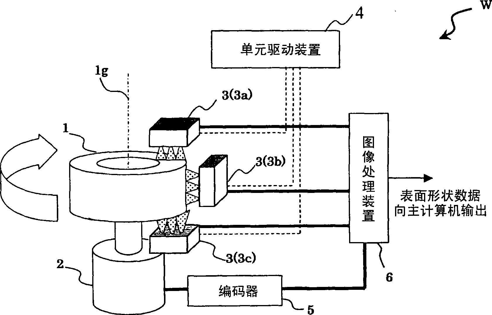
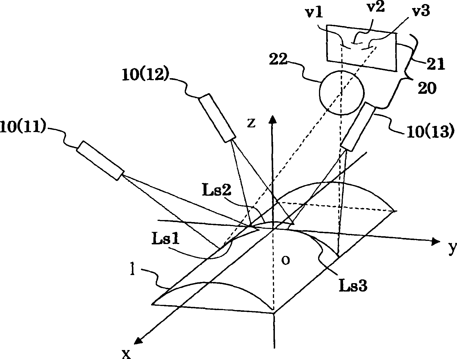
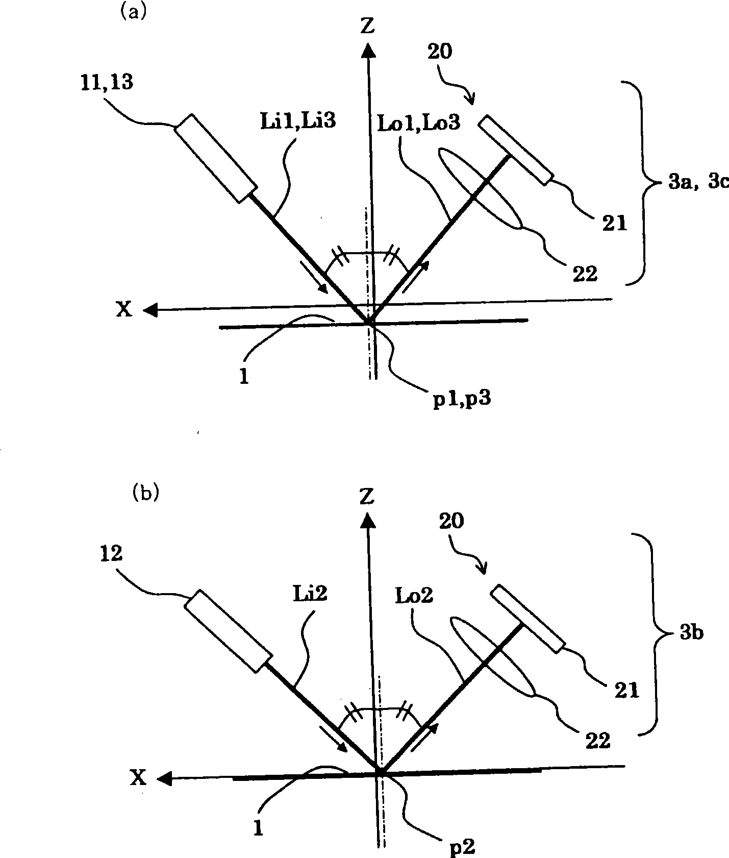
[0101] here, figure 1 is a diagram showing a schematic configuration of a tire shape measuring device W according to an embodiment of the present invention, figure 2 is a diagram schematically showing the three-dimensional arrangement of the light source and the camera in the sensor unit included in the shape measuring device W, image 3 is a diagram schematically showing the arrangement of a linear light source and a camera in a sensor unit when viewed from a specific direction (Y-axis direction), Figure 4 is a diagram schematically showing the arrangement...


PUM


Abstract

A tire shape measuring system measures a surface shape on the basis of an image of a line of light (a light section line) emitted to a surface of a relatively rotating tire using a light-section method. The shape measuring system includes a light projector (10) for emitting a plurality of lines of light onto a tire surface in directions different from a direction in which the height of the surface is detected so as to form a plurality of separate light section lines and a camera (20) for capturing images of the light section lines in directions in which chief rays of the lines of light are specularly reflected by the tire surface. The shape measuring system individually detects the coordinates of the light section lines from images of pre-defined independent image processing target areas for each captured image and calculates the distribution of the surface height using the detected coordinates. Thereby, clear images of light section lines can be obtained at high image of the light section lines capturing speed without reinforcing the strength of lines of light, and calculating load of image processing needed by light section lines detection is reduced.

Description

technical field [0001] The present invention relates to a method of detecting the surface shape of a tire by capturing an image of linear light (image of a light cutting line) irradiated on the surface of a tire that is relatively rotating, and performing shape detection by a light cutting method based on the captured image. Tire shape measuring device. Background technique [0002] In production sites, for the purpose of product quality control and the like, it is often required to measure the surface shape (surface height distribution) of an object at high speed and without contact. [0003] A tire has a structure in which various materials such as rubber, chemical fibers, and steel wires are laminated. If there is an uneven part in the laminated structure, a bulge is called a bulge in a part that is relatively weak in pressure resistance when inflated. ridges (protrusions), or depressions (recesses) called pits or low-pressure areas. Tires with shape defects such as den...

Claims


Application Information

Patent Timeline
Patent Type & Authority Applications(China)
IPC IPC(8): G01B11/24
Inventor 高桥英二迫田尚和森本勉
Owner KOBE STEEL LTD
Why Eureka
Try Eureka