Luminous transmittance measuring device

A technology of light transmittance and light-emitting devices, which is applied in the direction of transmittance measurement, etc., can solve problems such as the difficulty in aligning the transmitting unit and receiving unit, the inability to realize the networking of the automatic detection system, and measurement errors, so as to save the drag of the connection and improve the convenience of operation The effect of reducing measurement error

Inactive Publication Date: 2009-02-11
SHANGHAI SIPAI AUTOMATION INSTR ENGCO
View PDF0 Cites 7 Cited by
  • Summary
  • Abstract
  • Description
  • Claims
  • Application Information

AI Technical Summary

Problems solved by technology

[0003] At present, there are many styles of light transmittance meters at home and abroad, but they all have fatal shortcomings, that is, it is difficult to align the emitting unit (light source) with the receiving unit, which easily leads to measurement errors
Both the transmitting unit and the receiving unit have power connections, which brings inconvenience to the operation when measuring the light transmittance of the front window glass; both can only display the measured value on the spot, and cannot realize the networking of the automatic detection system

Method used


Image

  • Luminous transmittance measuring device

Examples


Embodiment Construction

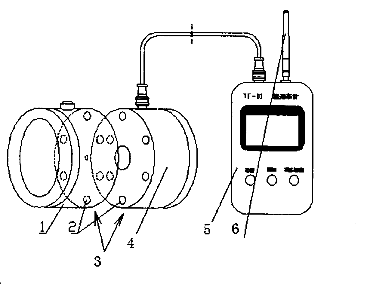
[0009] Depend on figure 1 As shown, a light transmittance meter includes a transmitting unit 1, a receiving unit 4, and a display unit 5. It is characterized in that the transmitting unit 1 and the receiving unit 4 are respectively placed on the same center line of the separate housing, and the transmitting unit 1 The rear end of the housing and the front end of the housing of the receiving unit 4 are each provided with a magnetic steel plate 3 which is composed of a plurality of NS magnetic poles 2 facing magnets, an LED light-emitting device is placed in the center of the transmitting unit 1, and a silicon photocell is placed in the center of the receiving unit 4 The receiving device detects the light emitted by the transmitting unit 1, and the output of the receiving unit 4 is connected to the display unit 5; the transmitting unit 1 is powered by a dry battery; the display unit 5 is equipped with a transmitting antenna 6, and the light transmittance meter is connected to the...


PUM


Abstract

The invention discloses a transmittance meter which comprises an emitting unit, a receiving unit and a display instrument. The transmittance meter is characterized in that the emitting unit and the receiving unit are respectively positioned on the identical central line of the casings thereof, a magnetic steel plate composed of a plurality of magnets with mutually opposite N magnetic poles and S magnetic poles is respectively positioned at the rear end of the casing of the emitting unit and at the front end of the casing of the receiving unit, an LED light emitting device is positioned in the center of the emitting unit, a silicon photocell receiving device is positioned in the center of the receiving unit, and the output of the receiving unit is connected with the display instrument. The emitting unit adopts a dry battery for power supply; ZigBee wireless communication is adopted between the transmittance meter and an upper computer. The transmittance meter has the advantages that the disadvantages of similar products at home and abroad are overcome, the instrument alignment can be convenient when the transmittance is measured, the environmental impact is avoided, and the measurement error is reduced; the emitting unit adopts the battery for power supply so as to eliminate a connecting line, therefore, the operation convenience is improved; the ZigBee wireless communication function is added so as to be convenient for networking with the upper computer.

Description

technical field [0001] The invention relates to an instrument for measuring the light transmittance of glass, in particular to an instrument for detecting the light transmittance of glass on a motor vehicle which affects the front view and the side view. Background technique [0002] With the rapid development of transportation, the number of automobiles in our country has increased rapidly, and the safety technical performance of automobiles will directly affect the safety of people's lives and property. For this reason, the national standard GB7258-2004 "Technical Conditions for Motor Vehicle Operation Safety" requires that "the driver's cab must ensure the driver's front view and side view, and the visible light transmittance of the glass other than the windshield used for the driver's viewing area is not high. It is allowed to be less than 70% (article 11.6.4). There are also relevant regulations in the industry standard GA468-2004 "Motor Vehicle Safety Inspection Items ...

Claims


Application Information

Patent Timeline
Patent Type & Authority Applications(China)
IPC IPC(8): G01N21/59
Inventor 蒋宇晨徐弢杨之仪高文翔袁雄鹤
Owner SHANGHAI SIPAI AUTOMATION INSTR ENGCO
Why Eureka
Try Eureka