Reinforcing method for suspending anchor point of engine and suspending point assembly

An engine mount, fixed point technology, applied in power plant, jet propulsion device, internal combustion propulsion device, etc., can solve the problem of unresolved strengthening effect, the effect of strength meeting the requirements, the concentration of force at the mounting point, etc. The effect of shortening the development cycle, increasing the intensity, and saving development costs

Active Publication Date: 2009-02-18
CHERY AUTOMOBILE CO LTD
View PDF0 Cites 16 Cited by
  • Summary
  • Abstract
  • Description
  • Claims
  • Application Information

AI Technical Summary

Problems solved by technology

However, from the point of view of general layout, such arrangement of suspension points takes up a lot of space inside the longitudinal beam, which makes it impossible to match other powertrains, and also brings great difficulties to the arrangement of other parts of the entire front cabin. difficulty
[0006] The traditional strengthening method utilizes the 100% bonding of sheet metal and sheet metal to achieve the strengthening effect, but this directly leads to the waste of raw materials, difficulties in welding operations, and whether the strength effect meets the requirements, etc.
For the suspension point on the wheel cover, although the problem of the layout space of the engine compartment has been solved, there are hidden dangers in terms of the strength of the suspension point. The thickness of the sheet metal design of the wheel cover is less than 1mm. The area of ​​the wheel cover is relatively large, and the force on the suspension point is too concentrated, and the reinforcement plate is designed to fit the wheel cover sheet metal in a large area. This not only does not solve the role of reinforcement, but is counterproductive.

Method used


Image

  • Reinforcing method for suspending anchor point of engine and suspending point assembly
  • Reinforcing method for suspending anchor point of engine and suspending point assembly
  • Reinforcing method for suspending anchor point of engine and suspending point assembly

Examples


Embodiment Construction

[0054] In the following, the present invention will be further explained in conjunction with the accompanying drawings:

[0055] Such as figure 1 As shown, the traditional way of strengthening the mounting points of the engine wheel cover suspension is only the 100% shape fit of the two layers of sheet metal, which not only increases the difficulty of welding, but also causes the waste of raw materials, and also increases the weight of the car body.

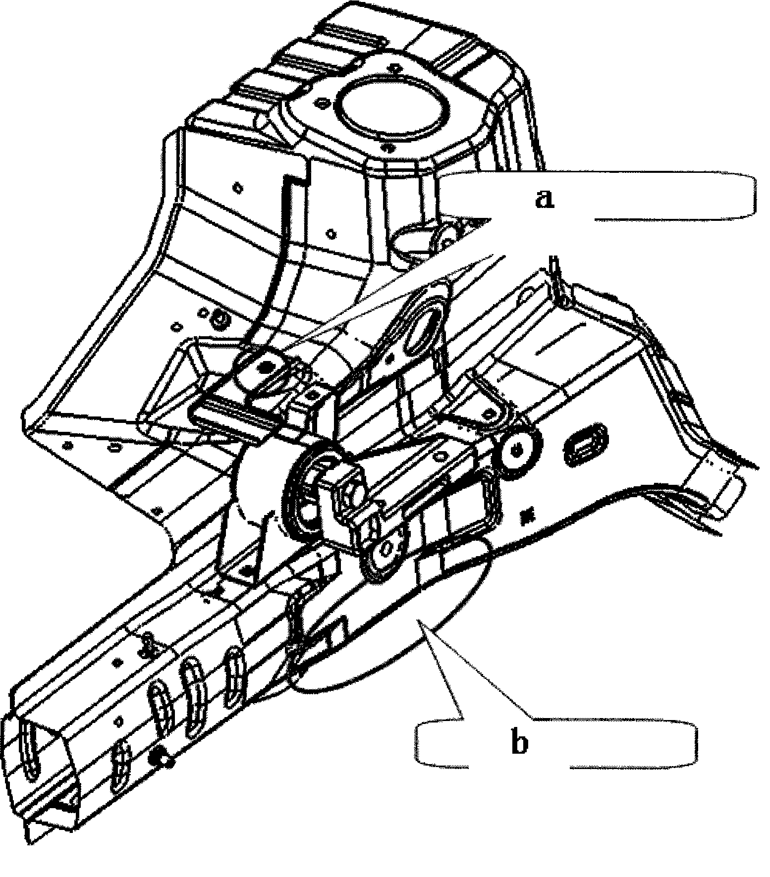
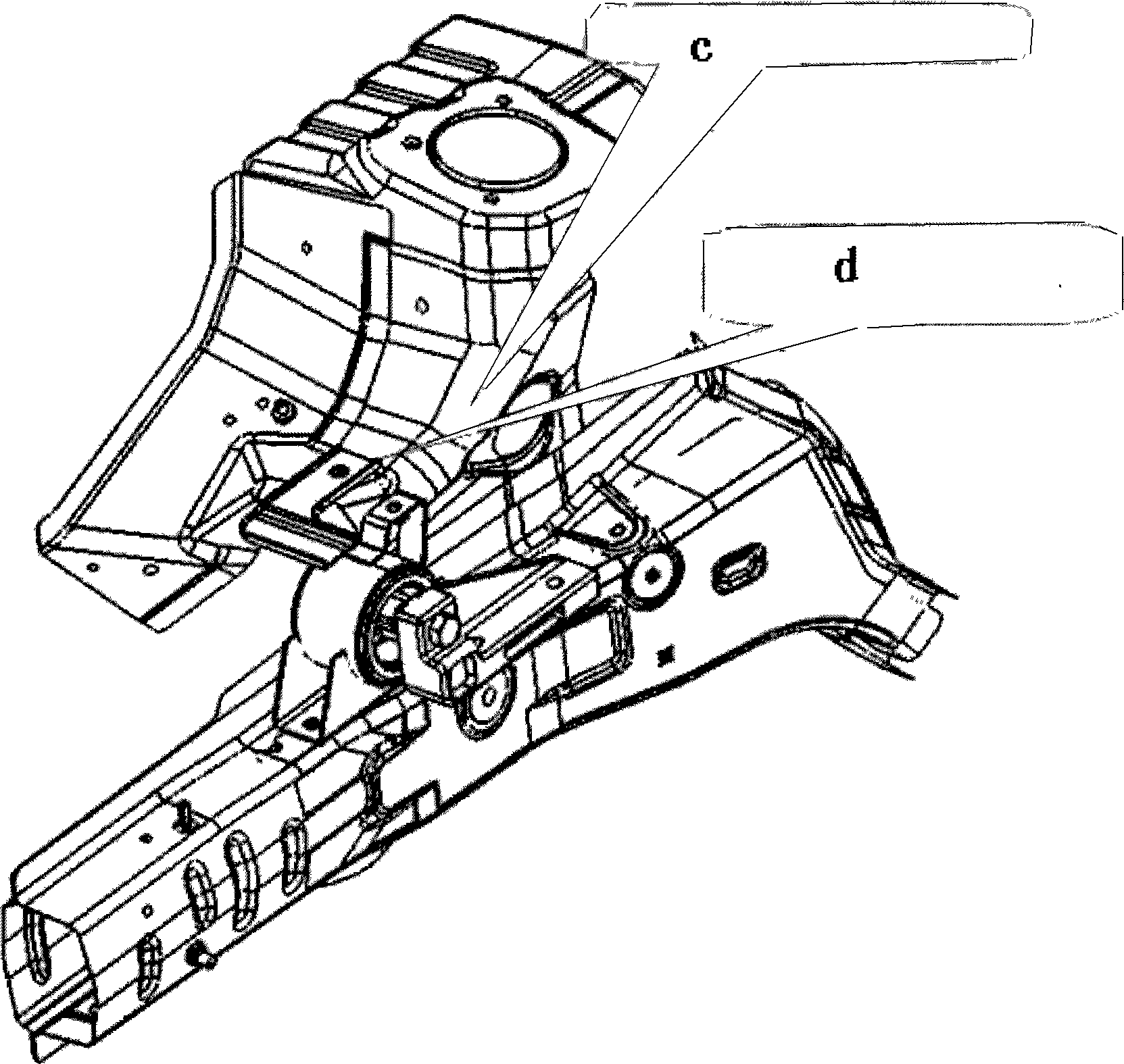
[0056] From Figure 2-3 It can be seen from the above that such a suspension point arrangement can save a lot of space around the front cabin longitudinal beam and also improve the heat dissipation performance of the front cabin.

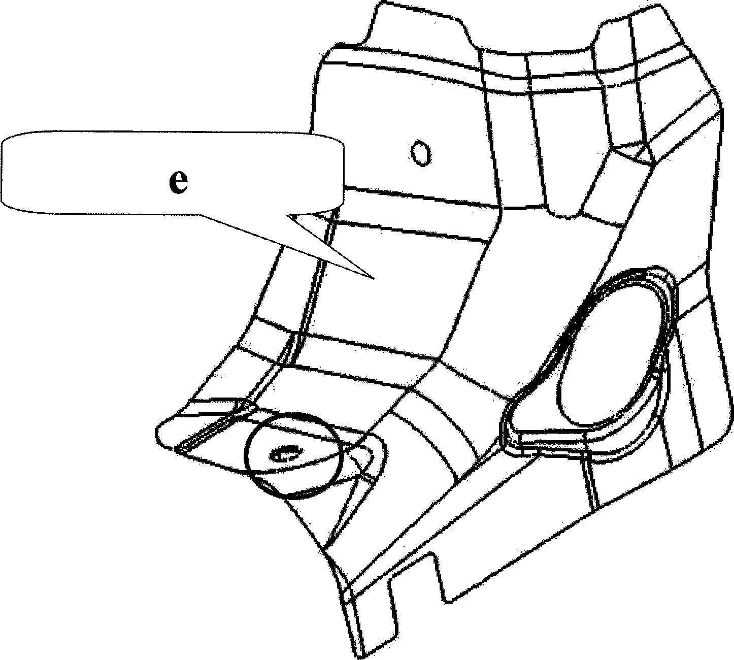
[0057] Figure 4-10 It can fully demonstrate the advantages of the new wheel cover suspension strengthening method. The invention has a simple structure and compact layout, which effectively improves the strength of the engine wheel cover suspension point, and makes the suspension and the body fixed firml...


PUM


Abstract

The invention relates to a method for strengthening a suspension fixed point of an engine and a suspension point assembly thereof. In a suspension support assembly of the engine, two suspension points are fixed on a carling assembly (4); one suspension point is fixed on a wheel cover and is formed by welding a sheet metal body and a sheet metal of the wheel cover; and eight welding spots are distributed on the circumference of the suspension point and uniformly distributed in the form of a long circle so as to form a welding spot closed loop, wherein the sheet metal body adopts a semi-enclosed cavity-shaped stiffening sheet, namely a stiffening sheet which adopts the structure of an enclosed cavity. The method and the structure can effectively improve the intensity of the suspension points of the engine which are distributed on the wheel cover, simultaneously can increase the space utilization rate of an engine compartment and provide a wider space for auto-builders to realize vehicle models with a plurality of configurations in one compartment, and can also save the development cost and shorten the development period of a whole vehicle.

Description

Technical field [0001] The present invention relates to a car body structure strengthening design, in particular to a new type of engine suspension strengthening method and its assembly in which a certain point of the engine suspension is arranged on the wheel cover. Arrange a certain suspension point on the wheel cover and how to reasonably strengthen this suspension installation point. Background technique [0002] With the rapid development of today's automobile industry, customers have higher and higher requirements for the diversified displacement of family car engines. It is a trend in the development of today's cars to match a car body with a variety of displacement engines. For mini-cars, due to the limitation of the space of the engine compartment itself, the traditional layout method can no longer meet the requirements of the development trend of today's cars. The traditional engine suspension fixing points are all arranged on the body rails, but in many cases there is ...

Claims


Application Information

Patent Timeline
Patent Type & Authority Applications(China)
IPC IPC(8): B60K5/12B60K5/00
Inventor 荣升格杨金秀高发华王灿军高新华
Owner CHERY AUTOMOBILE CO LTD
Why Eureka
Try Eureka