Stable combustion anti-slag gap type W-shaped flame boiler apparatus

An anti-slagging and gap-type technology, applied in combustion equipment, lighting and heating equipment, etc., can solve the problems of unreasonable combustion structure, easy slagging in the lower furnace, poor flame stability of pulverized coal gas flow, etc. performance, improve flame stability, and organize reasonable effects

Active Publication Date: 2009-02-18
HARBIN INST OF TECH
View PDF0 Cites 29 Cited by
  • Summary
  • Abstract
  • Description
  • Claims
  • Application Information

AI Technical Summary

Problems solved by technology

[0003] The purpose of the present invention is to solve the problems of unreasonable combustion structure, easy slagging in the lower furnace and poor flame stability of the

Method used


Image

  • Stable combustion anti-slag gap type W-shaped flame boiler apparatus
  • Stable combustion anti-slag gap type W-shaped flame boiler apparatus
  • Stable combustion anti-slag gap type W-shaped flame boiler apparatus

Examples


specific Embodiment approach 1

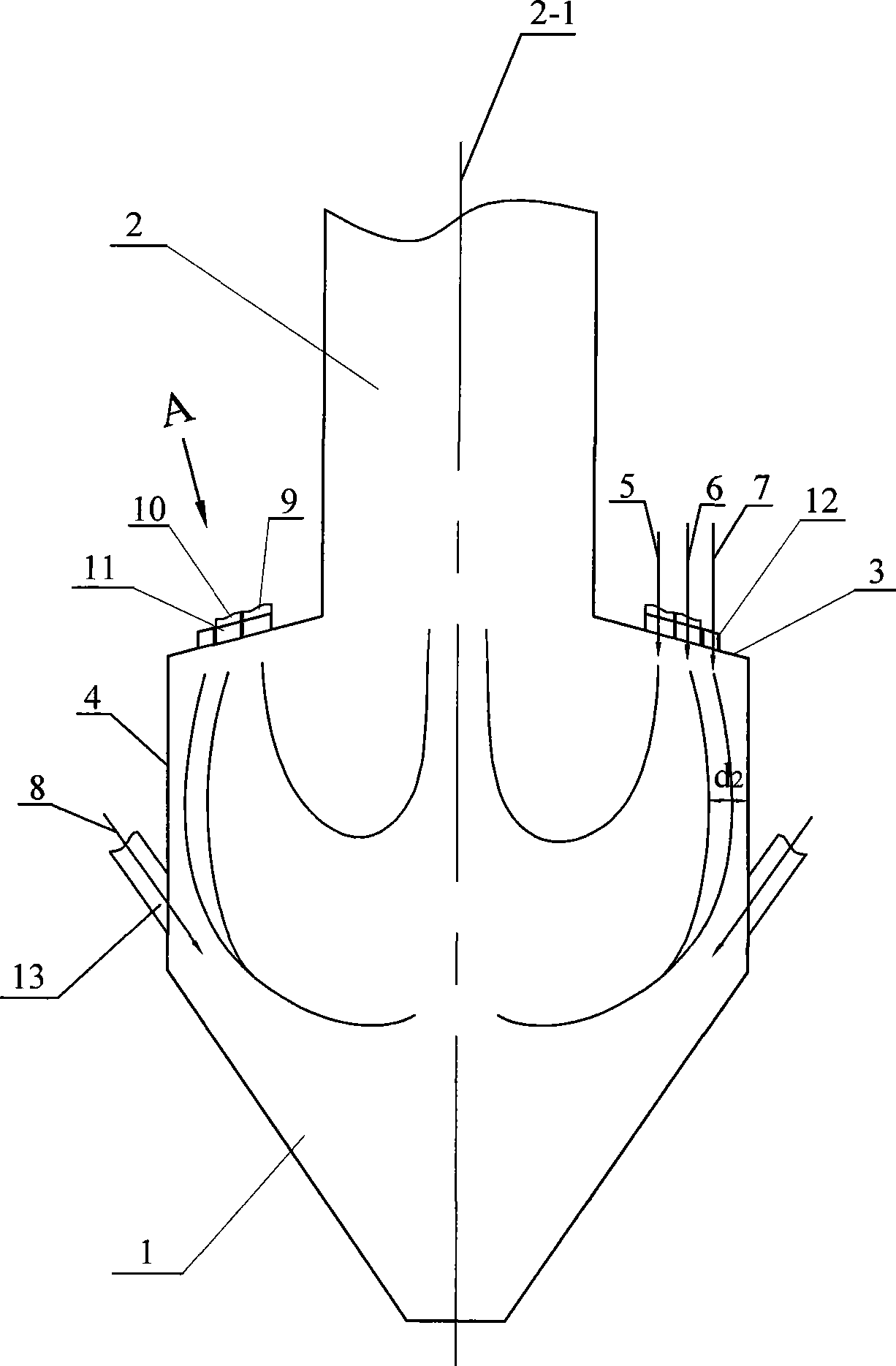
[0007] Specific implementation mode one: combine figure 1 and figure 2 This embodiment is described. This embodiment is composed of the lower furnace 1, the upper furnace 2, the front and rear arches 3 and the front and rear water walls 4. The upper furnace 2, the front and rear arches 3, the front and rear water walls 4 and the lower furnace 1 are from top to bottom. The bottom is connected into one body, the lower part of the front and rear walls 4 is provided with two symmetrical rows of tertiary air nozzles 13, and the front and rear arches 3 are provided with primary air nozzles 9, exhaust air nozzles 10 and secondary air nozzles 11. The anti-slagging secondary air spout 12 is also provided on the front and rear arches 3; the primary air spout 9 is opened on the front and rear arches 3 near the furnace center 2-1 side, and the secondary air spout 11 and the primary air spout 9 are arranged at intervals, the anti-slagging secondary air nozzles 12 are opened on the front...

specific Embodiment approach 2

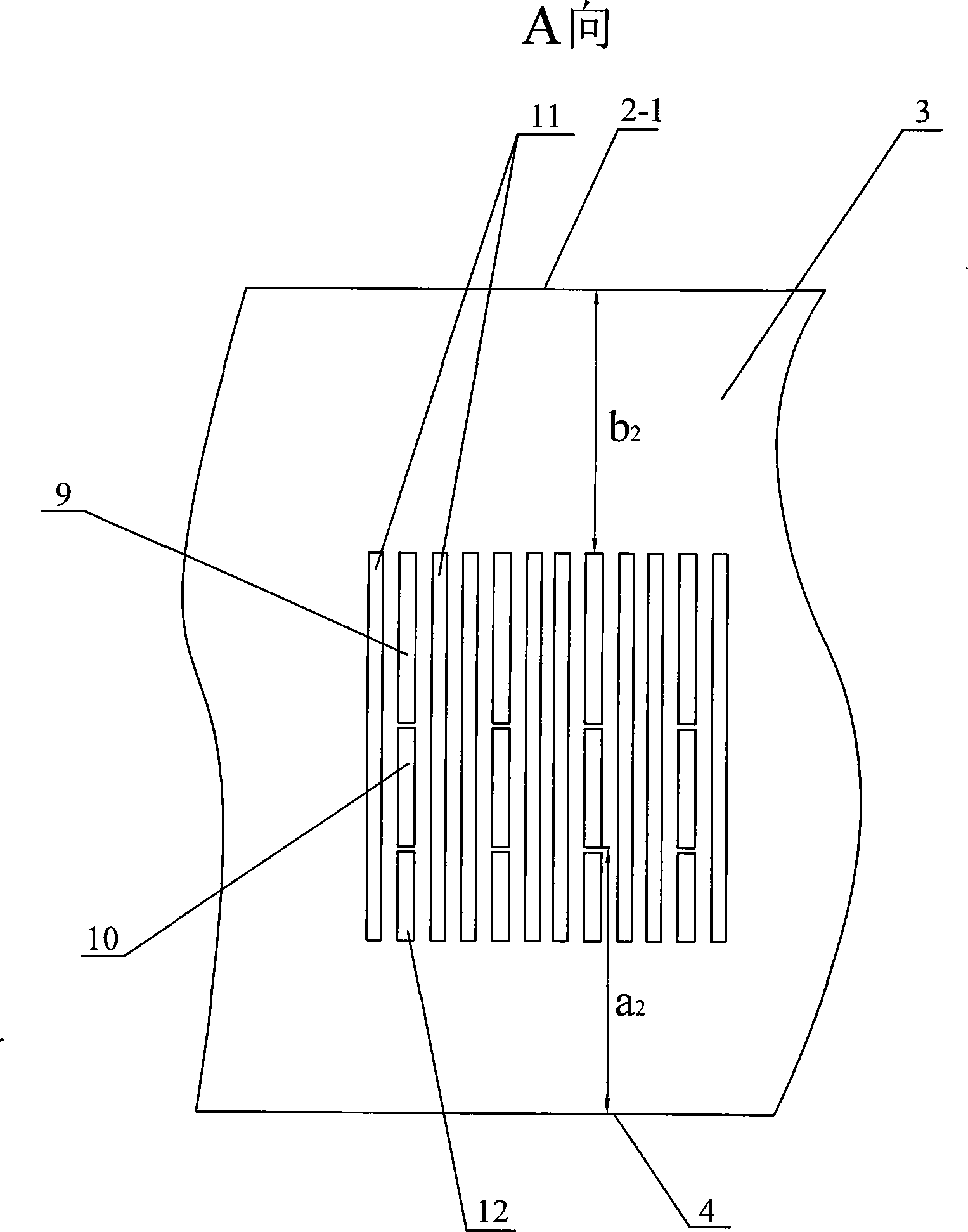
[0008] Specific implementation mode two: combination figure 2 Describe this embodiment, the upper edge of the secondary air nozzle 11 of this embodiment is flush with the upper edge of the primary air nozzle 9, and the lower edge of the secondary air nozzle 11 is flush with the lower edge of the anti-slagging secondary air nozzle 12 , the distance from the upper edge of the primary air nozzle 9 to the hearth center 2-1 is b 2 . In this way, the primary air jet is closer to the center of the high-temperature furnace (b 2 1 ), the flame stability of pulverized coal flow is better. Other components and connections are the same as those in the first embodiment.

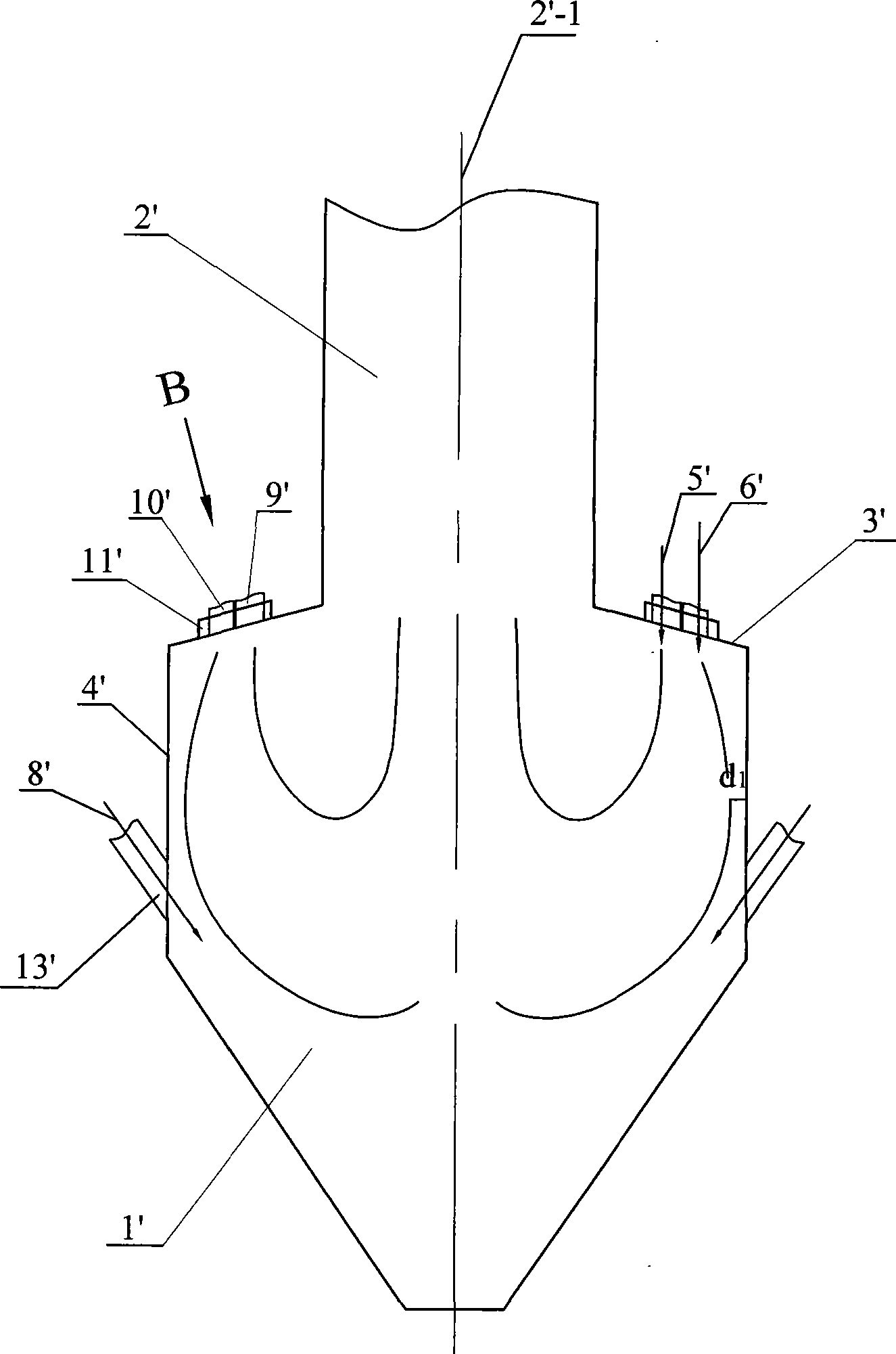
[0009] Depend on figure 1 and figure 2 Compared, image 3 and Figure 4 It can be seen from the comparison that the exhaust gas is farther away from the water-cooled walls of the front and rear walls of the lower furnace after the arrangement structure of the present invention is adopted in the slot type W-type f...


PUM


Abstract

Disclosed is a stable-combustion slagging resistant slit W-type flame boiler device which relates to a W-type flame boiler combustion device. The invention solves the problems of unreasonable combustion organization, easy slagging in the lower hearth and the bad stability of the pulverized coal airflow flame found in the slit W-type flame boiler in the prior art. The front arch and rear arch (3) of the invention are provided with a primary air spout (9), an exhaust spout (10), a secondary air spout (11) and a slagging resistant secondary air spout (12); the primary air spout (9) is arranged on the front and the rear arch (3) close to the central side of the hearth; the secondary air spout (11) and the primary air spout (9) are arranged alternately; the slagging resistant secondary air spout (12) is arranged on the front arch and the rear arch (3) close to the water cooling wall side of the front wall and the back wall and is arranged on the same side where the primary air spout (9) is arranged; the exhaust spout (10) is arranged between the primary air spout (9) and the slagging resistant secondary air spout (12); a combustor spout is distributed through the hearth center (2-1) as the symmetrical surface. The stable-combustion slagging resistant slit W-type flame boiler device has the advantages of reasonable combustion organization, reducing the slagging of the lower hearth and good stability of the pulverized coal airflow flame during the operating process of the slit W-type flame boiler.

Description

technical field [0001] The invention relates to a W-shaped flame boiler combustion device, which belongs to the technical field of W-shaped flame boiler combustion. Background technique [0002] W-type flame combustion boiler is a boiler specially designed for burning anthracite and lean coal. It has unique advantages in burning low volatile anthracite and lean coal. The slot-type W-flame boiler is named after the direct-flow slot burner. It usually has the following characteristics: the primary air, exhaust gas and secondary air are arranged on the arch, and the primary air (the concentration of pulverized coal is relatively high, and its pulverized coal content is about Accounting for 90% of the total amount of pulverized coal) on the side close to the center of the furnace is susceptible to being heated by high-temperature flue gas and ignites, lack of gas (the concentration of pulverized coal is low, and its pulverized coal content accounts for about 10% of the total pul...

Claims


Application Information

Patent Timeline
IPC IPC(8): F23C7/00F23C9/00F23J9/00
Inventor 李争起况敏陈智超阮成武张福成
Owner HARBIN INST OF TECH
Why Eureka
Try Eureka