

Method, apparatus and system for transmitting data
A data transmission and data packet technology, applied in the field of data transmission, can solve the problem of low data packet transmission efficiency, and achieve the effect of improving transmission efficiency and efficiency
- Summary
- Abstract
- Description
- Claims
- Application Information
AI Technical Summary
Problems solved by technology
Method used
Image

Examples
Embodiment 1
[0041] Embodiments 1 and 2 will mainly be described by taking protocol header compression in an Ethernet (Ethernet) scenario as an example, while other embodiments will illustrate protocol header compression in other scenarios. Embodiment 1 and Embodiment 2 will be described by taking the implementation of common compression of protocol headers of each layer as an example:
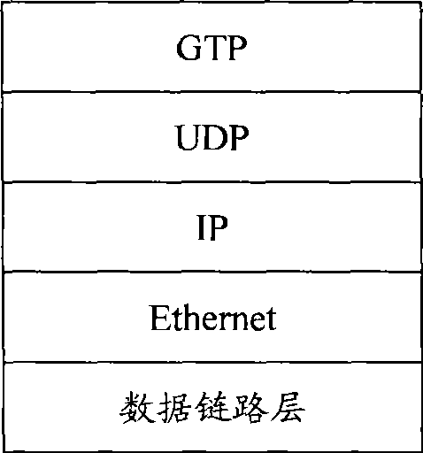
[0042] Such as Figure 2a As shown, it is a structural diagram of the S1 / X2 protocol stack, including a GTP protocol header, a UDP protocol header, an IP protocol header, and a data link layer protocol (Dala link layer). At least one protocol header among the GTP protocol header, the UDP protocol header and the IP protocol header can be compressed. The compression of subsequent embodiments can be referred to together Figure 2a ,Will Figure 2a as a comparison chart.
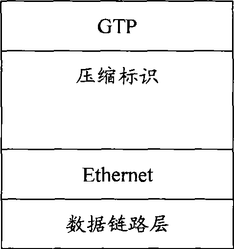
[0043] Embodiment one, such as Figure 2b As shown, the compression method is: UDP / IP is compressed into compressed identification byt...
Embodiment 2
[0048] Embodiment two, such as Figure 2c As shown, the compression method is: encapsulating the GTP protocol header into the Ethernet frame, and a schematic diagram of the compressed protocol stack structure.
[0049] The method of this embodiment may be: receiving the data packet based on the GTP protocol encapsulation sent by the base station controller, encapsulating the GTP packet into an Ethernet frame, and sending the compressed data packet of the protocol header to the base station; the subject of the above-mentioned execution may be a transmission aggregation device .
[0050] Encapsulate the GTP packet directly into the Ethernet frame, and GTP can be carried by a dedicated UDP port. Therefore, the MAC layer of the Ethernet interface can be distinguished by using a dedicated port. As shown in Table 2, it can be defined in the MAC header type (Type) area A special mark identifies that the Ethernet frame directly carries the GTP message, or it can be defined by expandi...
Embodiment 3
[0065] Embodiment 3, the compressed protocol header includes a compressed application layer protocol header. The method of this embodiment may be: receiving a data packet encapsulated based on the GTP protocol sent by the base station controller, compressing the application layer protocol header, and sending the compressed protocol header. The data packet is sent to the base station; the subject of the above execution may be a transmission aggregation device.
[0066] The above-mentioned compressed application layer protocol header takes GTP protocol header compression as an example, and the complete header format of the GTP protocol is as shown in Table 4:
[0067] Table 4 GTP complete header format
[0068]
[0069] The complete header format of the GTP protocol is applicable to GTP-U and GTP control plane protocol (GPRSTunneling Protocol for control plane, GTP-C), and the length is variable, and the minimum is 8 bytes. There are three flags used to indicate the presence...
PUM
 Abstract
Description
Claims
Application Information