
Method for expanding the adjustment range of overload protection devices, associated overload protection devices and their use

A technology of overload protection and adjustment range, applied in emergency protection devices, parts of protection switches, protection switches, etc., can solve the problems of increased cost of current transformers and electronic equipment, inappropriate DC or DC component monitoring, etc., to improve matching , the effect of reducing the number of

Inactive Publication Date: 2009-02-18
SIEMENS AG
View PDF3 Cites 7 Cited by
  • Summary
  • Abstract
  • Description
  • Claims
  • Application Information

AI Technical Summary

Problems solved by technology

[0009] The disadvantage is that the use of current transformers and electronics increases costs, moreover, this solution is not suitable for monitoring DC or DC components

Method used


Image

  • Method for expanding the adjustment range of overload protection devices, associated overload protection devices and their use
  • Method for expanding the adjustment range of overload protection devices, associated overload protection devices and their use
  • Method for expanding the adjustment range of overload protection devices, associated overload protection devices and their use

Examples


Embodiment Construction

[0061] Hereinafter, various solutions that can realize the wide adjustment range of the present invention will be described by taking an overload relay with a bimetallic sheet and a heating winding as an example. The differences between the examples are described separately below, followed by a description of their functionality:

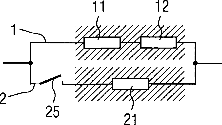
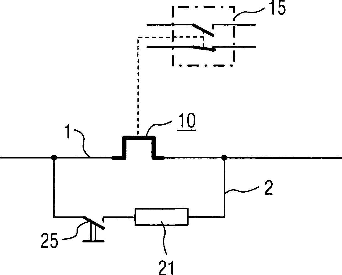
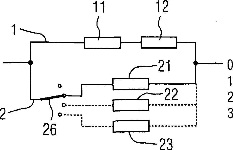
[0062] In each drawing, reference numeral 1 denotes a first branch, and reference numeral 2 denotes a second branch connected in parallel with the first branch. Furthermore, reference numeral 10 denotes a bimetal, which has a temperature-dependent switching function like the known bimetals from the prior art.

[0063] figure 1 The principle of impedance matching is shown: the highlighted area represents the thermal insulation between the bimetal branch and the parallel branch: specifically, the bimetal 11 and heating element 12 are arranged in the area of ​​branch 1, and the branch A diverter 21 is arranged in the area of ​​road 2 . The parallel ...


PUM


Abstract

In order to achieve thermomechanical overload protection with a broad adjustment range for protecting against overload currents, the live components carry an electrical current which is between the value of the overload current and zero. According to the invention, switching means are used which, in a preferred embodiment, switch the current, in parallel, from a first current branch to at least one second current branch, the parallel-connected at least one current branch carrying a partial current, which is between the value of the overload current and zero. In the associated overload protection device (102), contact means are provided which are associated with live components on two current branches (1, 2) which can be connected in parallel with one another, wherein at least one current branch can be switched on and off by the switching means. In an alternative embodiment, a first and a second current branch are connected electrically in series by switching means, as a result of which it is possible to switch over from an upper adjustment range to another, lower adjustment range of the broad adjustment range.

Description

technical field [0001] The invention relates to a method for extending the adjustment range of a thermomechanical overload protection device, wherein a user can predetermine a current adjustment value so that the protection device obtains a certain tripping characteristic (current-time curve). In addition, the present invention also relates to a corresponding thermomechanical overload protection device and its application. Background technique [0002] Overload relays or overload releases are used to prevent unacceptable excessive operating currents in electrical systems and electrical equipment (such as motors). Non-electronic overload relays or overload releases include thermal tripping mechanisms, such as bimetallic strips, snap-action discs, or the like, and are used to cut off the associated current branch in the event of an excessive operating current according to the current-time tripping characteristic curve. Road agencies operate. This mechanism is in particular a...

Claims


Application Information

Patent Timeline
IPC IPC(8): H01H71/74H01H71/16
CPCH01H71/74H01H71/7418H01H71/164H01H2071/749
Inventor 沃尔夫冈·费尔安德烈亚斯·克拉奇马弗里茨·波尔
Owner SIEMENS AG
Learn More