Power converter
A power conversion device and power conversion technology, applied in the direction of power consumption devices, control devices, power electronics modification, etc., can solve problems such as loss, and achieve the effect of reducing and suppressing thermal influence
- Summary
- Abstract
- Description
- Claims
- Application Information
AI Technical Summary
Problems solved by technology
Method used
Image

Examples
Embodiment 1
[0017]
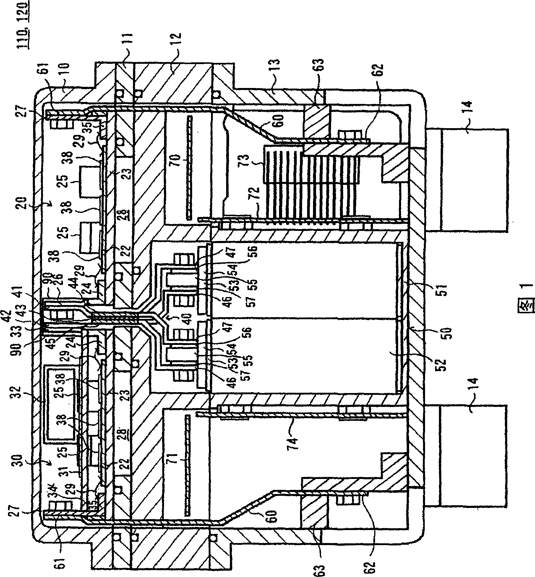
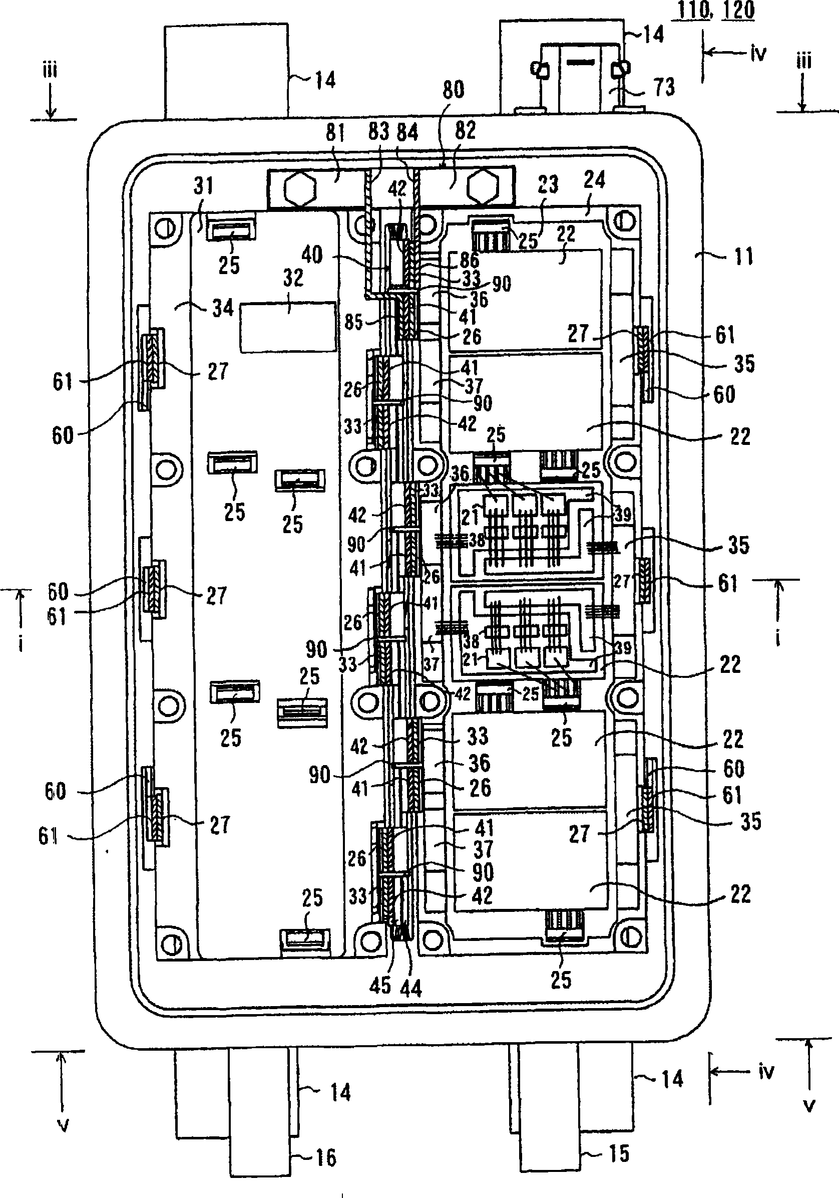
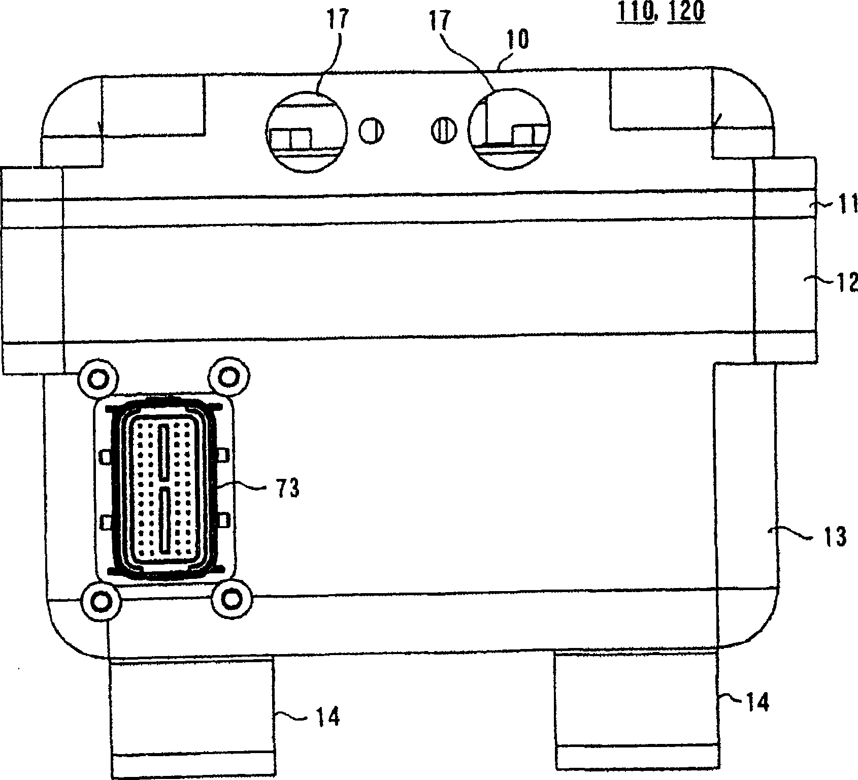
Below, refer to Figure 1- Figure 8 , and describe the first embodiment of the present invention.
[0018]
First, use Figure 8 Describe the hybrid electric vehicle of this embodiment.
[0019]
A hybrid electric vehicle (hereinafter referred to as "HEV") of this embodiment is an electric vehicle including two drive systems. One is an engine system using an internal combustion engine, the engine 104, as a power source. The engine system is mainly used as a driving source of the HEV. The other is an on-vehicle electric power system using motor generators 130 and 140 as power sources. The on-board power system is mainly used as the drive source of HEV and the power generation source of HEV.
[0020]
A front wheel axle 102 is rotatably supported at a front end portion of a vehicle body (not shown). At both ends of the front wheel axle 102, a pair of front wheels 101 are provided. Although not shown, the rear end portion of the vehicle body is rotatably suppor...
Embodiment 2
[0070]
Below, refer to Figure 9 , and describe the second embodiment of the present invention.
[0071]
This embodiment is an improved example of the first embodiment, and the same components are assigned the same symbols, and will not be described again.
[0072]
The difference between this embodiment and the first embodiment is that a third cooling cavity surrounded by the upper casing 10 and the second upper casing 19 is formed on the upper part of the cooling cavity containing the semiconductor modules 20 and 30, and the drive circuit A substrate 97 including a substrate, a control circuit substrate, and a connector substrate is accommodated therein.
[0073]
The wiring sheets of the semiconductor modules 20 and 30 and the substrate 97 are electrically connected by a wiring member 98 .
[0074]
The capacitor case of the capacitor 50 is omitted and replaced by pi-shaped legs of the second base 12 . Therefore, the π-shaped legs of the second base 12 are formed ...
Embodiment 3
[0077]
Next, a third embodiment of the present invention will be described with reference to FIG. 10 .
[0078]
This embodiment is an improved example of the first embodiment, and the same components are given the same symbols, and will not be repeated.
[0079]
The difference between the present embodiment and the first embodiment is that the drive circuit boards 70 and 71 together with the AC bus bars 60 and the terminal holder 63 are housed in the cooling chamber for housing the semiconductor modules 20 and 30 .
[0080]
In addition, a second cooling chamber is formed by the second base 12 below the cooling chamber in which the semiconductor modules 20 and 30 are accommodated, and further below, two third cooling chambers are formed by the second base 12 . The capacitor 50 is housed in the second cooling chamber; the control circuit board 74 is housed in one of the third cooling chambers; and the connector substrate 72 is housed in the other third cooling chamber. ...
PUM
 Abstract
Description
Claims
Application Information
 - R&D
- Intellectual Property
- Life Sciences
- Materials
- Tech Scout
- Unparalleled Data Quality
- Higher Quality Content
- 60% Fewer Hallucinations
Browse by: Latest US Patents, China's latest patents, Technical Efficacy Thesaurus, Application Domain, Technology Topic, Popular Technical Reports.
© 2025 PatSnap. All rights reserved.Legal|Privacy policy|Modern Slavery Act Transparency Statement|Sitemap|About US| Contact US: help@patsnap.com